Home | Contact Us | Submit Troubleshooting Info | Search | Help
Output | Software Solutions | Proofing | Color, Screening and Calibration | Scanning | Digital Photography | Consumables | POS
Home | Contact Us | Submit Troubleshooting Info | Search | Help
Output | Software Solutions | Proofing | Color, Screening and Calibration | Scanning | Digital Photography | Consumables | POS
|
|
|||||||||||||||||
Product |
|
||||||||||||||||
|
|
|||||||||||||||||
Background |
The objective of this procedure is to find the optimal drum speed for flexo plates at a resolution of 100 dpm (or any other resolution as required). Note: Test results depend on the plate type, so this test must be performed for each plate type that the customer uses. Test results do not depend on plate size or thickness. |
||||||||||||||||
|
|
|||||||||||||||||
Requirements |
Note: For devices with a magnetic drum, use a plate of the same type that does not have the steel back. This type of plate is provided by the plate manufacturer for calibration purposes. If such a plate is not available, follow the special instructions in step 1 of the Selecting the optimal drum speed section. |
||||||||||||||||
|
|
|||||||||||||||||
Procedure |
This procedure includes the following stages: Testing drum speed
 Note: You must also select the relevant screenset. For example: 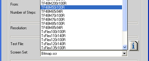
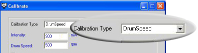
Note: Do not modify the value in the Intensity box at this time. (This value should be the value that you use for exposing: 600 mV or 900 mV, depending on the type of diode.)
Selecting the optimal drum speed
|
||||||||||||||||
Technical contact(s) |
Content owner: Viki Arviv |
||||||||||||||||
Date submitted |
22 Jun 2004 |
||||||||||||||||