Home | Contact Us | Submit Troubleshooting Info | Search | Help
Output | Software Solutions | Proofing | Color, Screening and Calibration | Scanning | Digital Photography | Consumables | POS
Home | Contact Us | Submit Troubleshooting Info | Search | Help
Output | Software Solutions | Proofing | Color, Screening and Calibration | Scanning | Digital Photography | Consumables | POS

 |
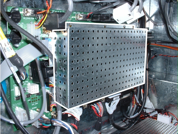
Turbo master control electronics (TMCE or MCE) board
Part number: 510P1P974A
Where used: All TMCE devices
Connectors | Description | Drawings | Indicators | Procedures
Description
The TMCE board is the main controller board for the device. It manages all imaging tasks and controls the actuators responsible for media loading and unloading. It does not include controls for the Spectrum or AL options, but it does support expanding to these options with satellite boards (GENINE boards).
For a detailed description, see:
Checking voltage supply test points helps to isolate problems resulting from connection and power supply failures. Reseat all connectors on the PCB assembly before checking voltage supply test points.
Important: Before servicing a board, review the information on the Shock and Electrostatic Discharge safety page.
Drawings
Procedures
- For detailed TMCE board connectivity procedures, see the MCE connectivity section of the Procedures page.
- For detailed TMCE board firmware procedures, see the Boards/firmware section of the Procedures page.
- For TMCE board troubleshooting items, see the Troubleshooting page.
Connectors
See MCE - Description of Connectors for a detailed description of each connector and test points.
Designator
Label on Board
Connector Type
Description
J1 EH_DATA SMB Hotlink to exposure head J2 EH_CNTL 44 pin HDSUB Exposure Head Control J3 PFO_E 1X2 Molex Minifit Jr Flyoff laser power connector J4 DIN_AS 37 pin DSUB Away side digital input connector J5 DIN_SPR 25 pin DSUB Spare digital input connector J6 DIN_HS 37 pin DSUB Home side digital input connector J7 SCON1 2X5 Molex Minifit Jr Expansion bus connector #1 J8 SCON2 2X5 Molex Minifit Jr Expansion bus connector #2 J9 - 2X10 header Logic analyzer header J10 SOL_DRV 2X13 Shrouded Solenoid Output Connector J12 LTPS 1X6 MTA Load ramp sensor connector J13 CA_PWR 3X3 MinimateNLock Carriage amplifier power connector J14 - 2X10 header Logic analyzer header J15 - 2X10 header Logic analyzer header J16 USR_IF 2X5 Shrouded User interface board connector J17 - 2X10 header Logic analyzer header J18 BMM 2X50 SMT BMM connector J19 PFO-S 1X8 Berg Polarised Plate flyoff connector J20 DRUM_ENC 15 pin HDSUB Drum encoder connector J21 REG 2X7 Shrouded Plate registration connector J22 - 2X10 header Logic analyzer header J23 - 2X10 header Logic analyzer header J24 RLY_DRV 2X4 Molex Minifit Jr Relay driver connector J25 VREG 2X4 PCB header Version register jumper connector - unpopulated option, footprint/pads only on PCB J26 CA_CNTL 2X10 Shrouded Carriage amplifier control connector J27 - Jumper Analog GND connection J28 JTAG 1X8 PCB header JTAG communications port J29 - 168 pin DIMM SDRAM connector J30 TEMP 2X6 Molex Minifit Jr Temperature sensor connector J31 - 2X10 header Logic analyzer header J32 - 2X10 header Logic analyzer header J33 - 2X10 header Logic analyzer header J34 - 2X10 header Logic analyzer header J35 DRUM_AMP 15 pin DSUB Drum amplifier connector J36 BS_TEMP 2X2 Molex Minifit Jr Alternate temperature sensor connector J37 DNGL_COMM 9 pin DSUB RS232 Dongle communications port J38 SPR_COMM 9 pin DSUB RS232 Spare communications port J39 WS_COMM 9 pin DSUB RS232 Workstation communications port J40 DIAG_COMM 9 pin DSUB RS232 Diagnostics communications port J41 BOOT Jumper BOOT jumper connector J42 WS_SCSI 68 pin SCSI SCSI communications connector J43 ANALOG0 6-pin MTA 4-20mA analog input J44 WS_TSP 68 pin SCSI TSP (turboscreening) connector J45 Analog Drum Control Jumper Analog Drum Amp control jumper Indicators (Status LEDs)
Name
Color
Description
POWER Green power indicator LCA.FAULT Red Lit when LCA is not programmed correctly RESET Red reset inidcator HEARTBT Green Heartbeat - indicates mode that TMCE is in (BBR,BOOT,MAIN) IDLE Green indicates processor idle time INTR Yellow Interrupt - lit when processor is in interrupt routine SERVC Red Service