Causes and Solutions
|
Cause:
Malfunctioning carriage electronics (in particular, the carriage drive board)
Solution:
A printable PDF of this carriage electronics troubleshooting guide is also
available.
Tools Needed:
- Ensure that all mechanical system checks have been accomplished. (See the list of Trendsetter 3244 carriage troubleshooting
procedures at the bottom of this page.)
- Check that the ALE, MPE, and DPE are properly seated and that the backplane voltages are
correctly set (+5VDC and +12VDC can be adjusted via adjustment potentiometers on PS1).
- Ensure that all carriage subsystem non-volatile storage (NVS) parameters are set in
accordance with factory parameters.
Trendsetter/Proofsetter Spectrum models: Ensure that media name and color match in both
the “media” and “hdm” subsystems for each media type. This subsystem
mismatch has been known to cause carriage runaway and stalling. See also the Carriage Stalling: Electrical/Mechanical Problems
troubleshooting procedure.
Note: It is good practice to back up all NVS settings before making any
NVS modifications.
- Check that carriage drive motor and all associated cabling is correctly seated in their
respective connectors.
- Check system voltages on the carriage drive board.
Note: Hazardous voltages are present on the carriage drive board.
You can locate the test points using the Carriage Motor Drive Schematics.
| Test Point |
Voltage |
Tolerance |
| TP7 |
+5VDC |
± 1% |
| TP8 |
+12VDC |
± 3% |
| TP9 |
-12VDC |
± 4% |
| TP11 |
+85VDC |
± 1.5% |
| TP12, 10, and 4 |
GND |
None |
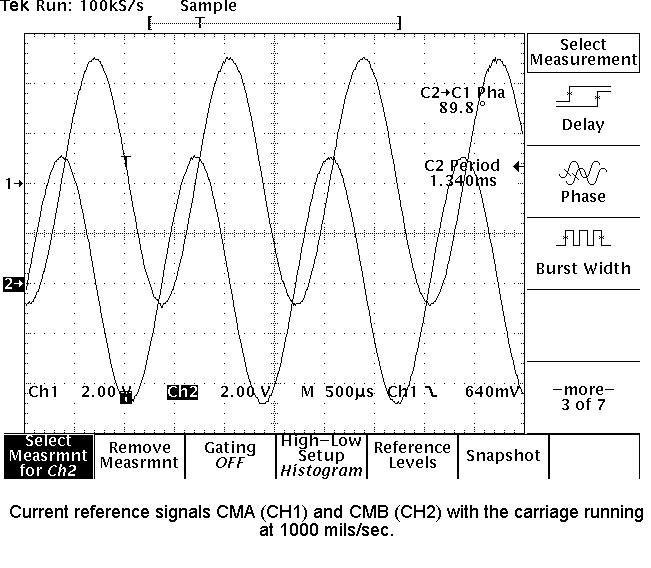
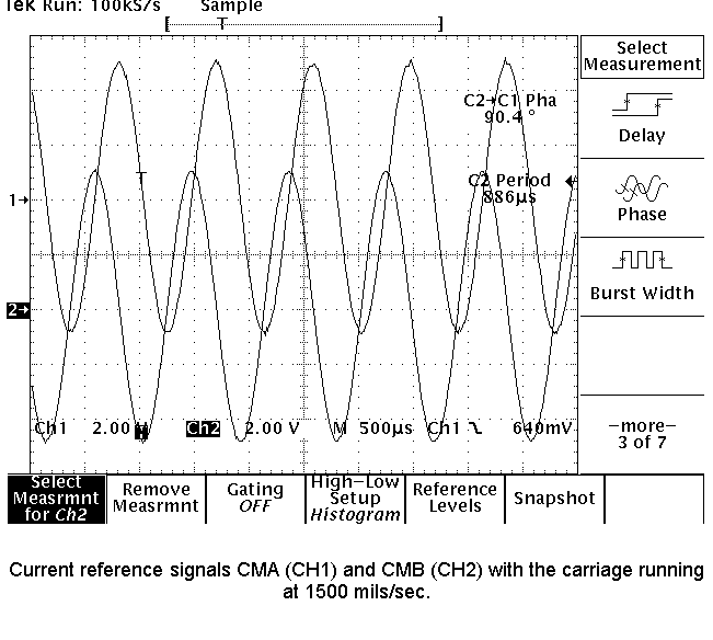
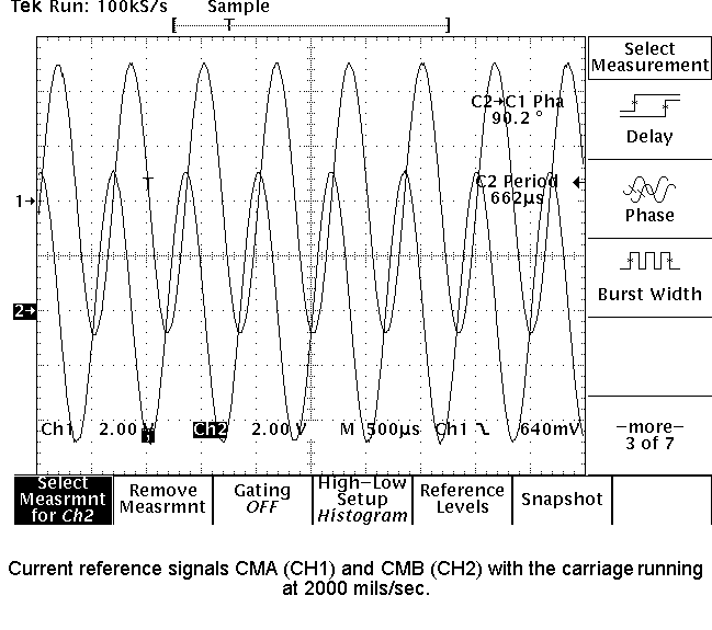
- Check the analog A current and B current reference signals from the ALE board are
correctly received at the carriage drive board.
Using two channels on the oscilloscope, place channel 1 on TP1 (signal name: CMA), place
channel 2 on TP5 (signal name: CMB), and connect both scope grounds on signal ground (DGND
or AGND).
Type carriage init to run the carriage home and reset the position
counter.
Run the carriage to the away position at maximum current at 1000 , 1500, and 2000
mils/sec. Type carriage moveto 40000 v
where v is the carriage velocity in mils/sec.
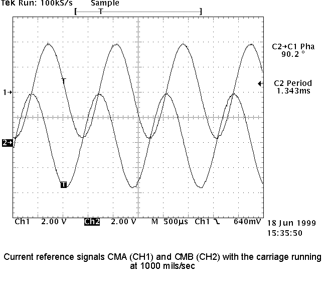
Check that the waveforms in Figures 1, 2, and 3 are correctly displayed with a carriage
mgain of 254. Pay particular attention to the waveform peak voltage, phase, and
distortion.
- Figure 1: Current reference signals CMA (CH1) and CMB
(CH2) with the carriage running at 1000 mils/sec.
- Figure 2: Current reference signals CMA (CH1) and CMB
(CH2) with the carriage running at 1500 mils/sec.
- Figure 3: Current reference signals CMA (CH1) and CMB
(CH2) with the carriage running at 2000 mils/sec.
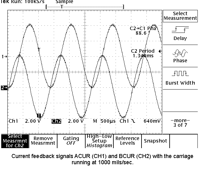
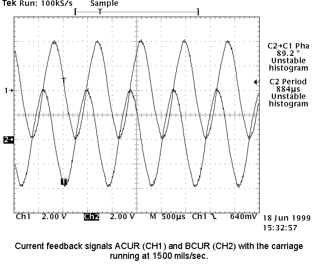
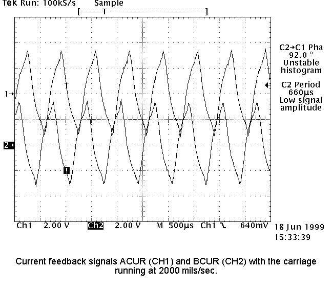
- Check the analog A current and B current feedback signals on the carriage motor drive
board. Repeat step 5 above with the scope probes on TP6 (A CUR) and TP3 (B CUR).Check that
the waveforms shown in Figures 4, 5, and 6 are displayed as correctly.
- Figure 4: Current feedback signals ACUR (CH1) and BCUR
(CH2) with the carriage running at 1000 mils/sec.
- Figure 5: Current feedback signals ACUR (CH1) and BCUR
(CH2) with the carriage running at 1500 mils/sec.
- Figure 6: Current feedback signals ACUR (CH1) and BCUR
(CH2) with the carriage running at 2000 mils/sec.
- Reduce the carriage move current setting to 192 by typing
set carriage
        mgain 192
. Initialize the carriage.
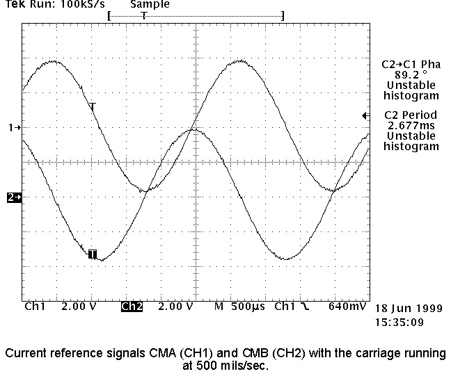
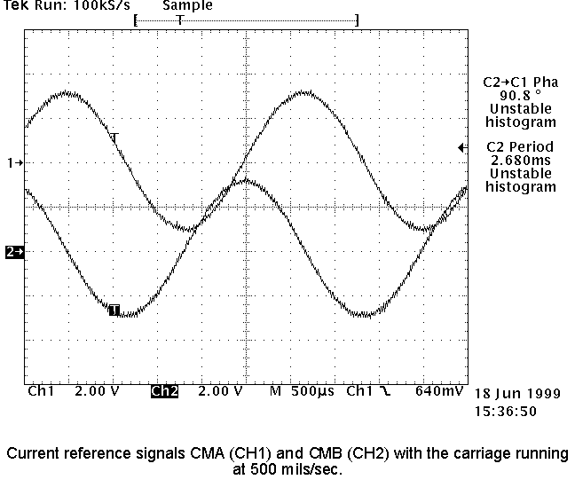
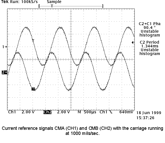
Repeat steps 5 and 6 at carriage velocities of 500 and 1000. Check that the waveforms
shown in Figures 7, 8, 9, and 10 are displayed correctly.
- Figure 7: Current reference signals CMA (CH1) and CMB
(CH2) with the carriage running at 500 mils/sec.
- Figure 8: Current reference signals CMA (CH1) and CMB
(CH2) with the carriage running at 1000 mils/sec.
- Figure 9: Current reference signals CMA (CH1) and CMB
(CH2) with the carriage running at 500 mils/sec.
- Figure 10: Current reference signals CMA (CH1) and CMB
(CH2) with the carriage running at 1000 mils/sec.
- Reset the carriage move gain to 254 and initialize the carriage.
- If the current reference and current feedback signals monitored in steps 5, 6, and 7
were displayed correctly, then this indicates that the Carriage Driver Board (CMD) and
Autoloader Electronics Board (ALE) are working correctly.
If the current reference signals are not displayed correctly then this indicates a
possible problem with the ALE board or carriage drive board.
If the current feedback signals are not displayed properly this indicates a problem may be
present in Carriage Driver Board or a poor connection present in one or more of the
following: Carriage Motor, Carriage Motor Cable, Common Mode Choke.
- If the carriage continues to stall, other electrical troubleshooting options include:
Remove or replace common mode choke (10-3790) from the carriage motor drive board and plug
the carriage drive cable (10-3270) directly into the carriage drive board.
Replace the cable (10-3270) connecting the carriage motor to the carriage drive board.
Replace the carriage motor.
|