Home | Contact Us | Submit Troubleshooting Info | Search | Help
Output | Software Solutions | Proofing | Color, Screening and Calibration | Scanning | Digital Photography | Consumables | POS
Home | Contact Us | Submit Troubleshooting Info | Search | Help
Output | Software Solutions | Proofing | Color, Screening and Calibration | Scanning | Digital Photography | Consumables | POS
Note: Check SAP for up-to-date information.
Air Supply
Autoloader
Carriage
Chiller
Cooling system
Debris Removal
Dehumidifier Unit
Engine
Engine module
Exposure heads
Fan box
Film upgrade
Load ramp
Operator Interface
Panels
Power box
Trendsetter 3244—02-4154
Drawing not available | BOM
Air Supply Filter/Regulator—55-0318
Air Filter Regulator Assembly Photo
Particulate filter—55-0324
Replacement bowl—55-0690Coalescent filter—55-0325
Replacement bowl—55-0690Adsorption filter—55-0326
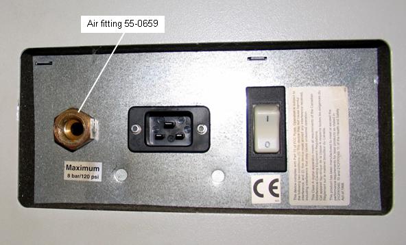
Replacement bowl—55-0694Brass air fitting on fanbox bulkhead, female, 1/2" (R) PT * 12 mm tube—55-0659 Photo
For pneumatic parts, see Manifold
Bore/flextube adapter kit—50-1242
Drawing| BOM
Note: Item #30 is an M6*10 set screw, 52-4116, used to secure the
collar added to each end of the carriage.
Item #70 is an M6*16 screw, 52-4226, that is the only screw that secures the
flex tube to the carriage. It is screwed in flush with the carriage and aligns
with a hole in the flex tube and the collar.
Carriage motor assembly—11-0403
Drawing
Carriage motor mount—50-1074
Drawing| BOM
Carriage drive belt—54-3256
Trendsetter air cooling kit—11-0592
Drawing not available | BOM
Trendsetter water cooling kit (hoses and cables)—11-0805
Uses an external chiller to water-cool the head
Drawing | BOM
External Chiller
Note: The external chiller is no longer available.
CRS TS3 and TS3/8 devices use a Heat exchanger.
DHU System—50-2442
BOM
Plate alignment—50-1298
Drawing not available| BOM
Plate exit door—50-1299
Drawing| BOM
TS3 Engine—50-1120
Drawing not available | BOM
TS3 Engine mechanical assembly—50-1361
Drawing | BOM
Ballscrew hanger UE—50-1052
Drawing| BOM
You must replace entire assembly #50-1052 since the bearing cannot easily be removed from the hanger.Clamp cylinder drive end TS3—50-1487
Drawing| BOMClamp cylinder encoder end—50-1486
Drawing| BOMDrum motor—50-1071
Drawing| BOMDrum motor timing belt—54-3894
Encoder—32-4047c
Drawing not available |BOM
Leading edge actuator (backbone)—50-1087
Drawing| BOM(If low profile clamps have been installed)
LE Clamp, low profile with dowel pin installed—500-03322A
kit includes LEC (50-2114A) and nine lead balance weights (59-3007)Pivot block kit—512-00260A
kit includes long (57-6851B) and short (57-7698B) pivot blocks(If high profile clamps have been installed, no UDRC)
Leading edge clamp assembly
See detail on page 2 of drum Drawingclamp body—57-2076
dowel—52-4343
pivot body, central—57-2077B
pivot body, ends—57-4772ALoad unload control panel—50-1096
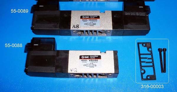
Drawing| BOMReplacement solenoid valve gasket—316-00003
photo of solenoid and gasketNorth magnetic clamp—50-1091
Drawing| BOMRoller CTP—50-1089
Drawing| BOMSouth magnetic clamp—50-1131
Drawing| BOMTrailing edge actuator (backbone)—50-1088
Drawing| BOMMicroswitch—15-3478
Microswitch bracket—57-8893A
TEC lock/unlock cylinder—55-0065
TEC lock/unlock cylinder—55-1210 (TS3 devices with S/N S001-S331 with FCO CA03931 completed)
TEC optical sensor—36-3210
Engine module—50-1300
Drawing| BOM
Frame—50-1366
Drawing not available | BOM
Upgrade Kit, TS# to TS3244V or TS3244X—02-4314
Drawing not available | BOM
Exposure head 2400 dpi, TEH—32-4005
Drawing not available | BOM
Exposure head 3200 dpi, thermal—32-4030
Drawing not available | BOM
Exposure head 2400 dpi, 48V, fast TEH 1.7—32-4052
Drawing not available | Drawing
TEH - 2400 dpi 20w, 192pix- Side-looking focus - 507-00263A (Side latch mount) - For use with Kodak Sword Excel plates only – See the upgrades page.
Fan box—11-0441
Drawing not available | BOM
Fan box wiring tray—11-0542
Drawing| BOMAir Supply Filter/Regulator—55-0318
Photo | BOMReplacement bowls and drain:
Black bowl/guard, no drain 55-0693
Black bowl/guard, manual drain 55-0694
Black bowl/guard, Auto drain, low flow 55-0690
Film & static upgrade kit—02-4220
Drawing not available | BOM
Film laser encoder guide TS—50-1463
Drawing| BOMFilm & static load ramp TS3—50-1462
Drawing not available | BOMScrews & expense parts, film kit TS3—50-1466
Drawing not available | BOMWire rack—50-1461
Drawing not available | BOM
Cylinder assembly, lower ramp—50-1537A
Drawing| BOM
Cylinder only—55-0066
EM Kit—11-0560
Assembly Drawing | BOM
Plate alignment assembly—50-1298
Drawing| BOM
Wire rack kit—50-1838
Drawing not available | BOM
Abort Switch Assembly—10-4044A
Abort switch—15-3066
Contact block—15-3067
Panels kit—50-1301
Drawing| BOM
Gas strut (cylinder) that supports front door—55-0564
Metal FAB panels TS3—50-1433
Drawing not available | BOM
Wire rack 3244 TS—50-1461
Drawing not available | 50-1461A-A BOM
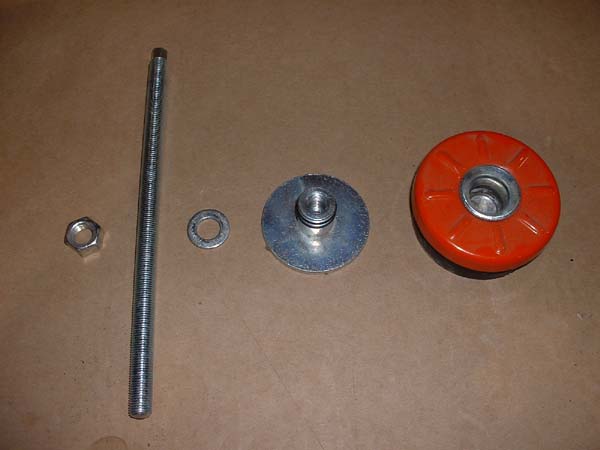
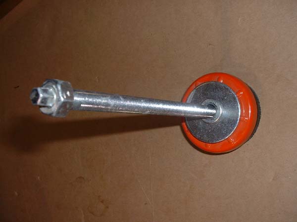
Leveling feet—59-3295A
Drawing | Photo of parts | Photo of assembly
Flex track—10-3209
Drawing| BOMKeyswitch SIO, Powerbox TS—11-0556
Drawing not available | BOMMain drive amp/Servoamp—15-3330
Power Supplies
PS1 through PS6—part numbers and description