Home | Contact Us | Submit Troubleshooting Info | Search | Help
Output | Software Solutions | Proofing | Color, Screening and Calibration | Scanning | Digital Photography | Consumables | POS
Home | Contact Us | Submit Troubleshooting Info | Search | Help
Output | Software Solutions | Proofing | Color, Screening and Calibration | Scanning | Digital Photography | Consumables | POS
Trendsetter 400/800 II serial numbers begin with TM
Auctus serial numbers begin with AM
Note: Check SAP for up-to-date information.
Air Supply
Carriage
Chassis
Cooling system (Fan box)
Debris Removal
Dehumidifier Unit
Disassembly kits
Drum amp/Main drive amp/Servoamp (Power box)
Engine
Exposure heads
Fan box
Load ramp
Manual load assembly
Panels
Power box
Trendsetter 4/8-page, TSM—02-4301D
Drawing not available | BOM
TS Base assembly,TSM—11-0973A
Drawing not available | BOMManual Load kit, TSM—11-0974A
Drawing not available | BOMManual Load Mainframe kit, TSM—11-0975
Drawing | BOMWire Rack kit for film—50-1461A
Drawing not available |BOMFilm option is a free upgrade that the customer can order. The installation is free for Full support service contract customers.Spectrum assembly—11-0992
Drawing not available |BOMSee Spectrum Assemblies for media kits
TS Autoloader Non-Rotator assembly, TSM—11-1058A
Drawing not available | BOMSee Autoloader Assemblies for detail
TS Autoloader Rotator assembly, TSM—11-1059A
Drawing not available | BOMSee Autoloader Assemblies for detail
TS ContinuousLoad Non-Rotator assembly, TSM—500-01143A
See ContinuousLoad Assemblies for detail
TS ContinuousLoad Rotator assembly, TSM—500-01144A
See ContinuousLoad Assemblies for detail
TS ContinuousLoad Non-Rotator Spectrum assembly, TSM—500-01145A
See ContinuousLoad Assemblies for detail
TS ContinuousLoad Rotator assembly, TSM—500-01146A
See ContinuousLoad Assemblies for detail
Blanking panel assembly—50-1947A
Drawing not available | BOMFly-off sensor kit, TSM—10-4996A
Drawing not available | BOM
Air Supply Filter/Regulator combination, TSM—55-1220A
Drawing | BOM
Filter replacement kit—332-00003 contains:5 micron filter
0.01 filter
O-rings
Filter bowl and guard assembly—55-1216
Bore/flextube adapter kit—50-1242A
Drawing| BOM
Note: Item #30 is an M6*10 set screw, 52-4116, used to secure the
collar added to each end of the carriage.
Item #70 is an M6*16 screw, 52-4226, that is the only screw that secures the
flex tube to the carriage. It is screwed in flush with the carriage and aligns
with a hole in the flex tube and the collar.
Carriage TEH, TSM—500-03033A
Drawing| BOM
Home/away tab—57-9278B
Carriage motor and pulley—11-1133C
Assembly Drawing | BOM
order entire assembly - do not order pulley or motor separately
Carriage motor mount—50-1623A
Drawing | BOM
Carriage drive board—503C01525B (see FCO CA00752)
Carriage belt
Timing belt (.080"P*184T,.375",NYLON)—54-3095 for 3:1 gear ratio (Use
set carriageto determine gear ratio)
Timing belt (.080"P*160T,.375",NYLON)—54-4253 for 2.16:1 gear ratio (Useset carriageto determine gear ratio)
Chassis assembly - 50-1664A
Drawing not available |BOM
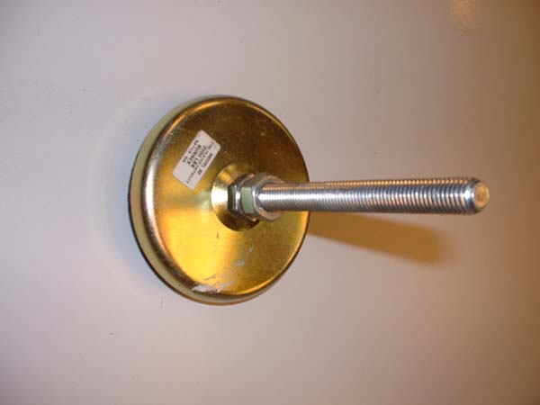
Leveling feet—59-3444 Photo
DHU System—50-2442A
BOM
Engine, TSM
500-02451C—Drawing | BOM
50-2439A (Trendsetter Spectrum)—Drawing | BOM
Ballscrew hanger—50-1620A
Drawing| BOM
You must replace entire assembly #50-1620A since the bearing cannot easily be removed from the hanger.Clamp cylinders (all*), drive (away) end—50-2683B
Drawing | BOM
*There are 3 individual cylinders included in the top level assembly noted above, if you require only single cylinders here are the part numbers:
LEC (away) - 50-1655A
TEC (away) - 50-1656A
ROLLER (away) - 50-1657AClamp cylinders (all*), home end—50-2684B
Drawing | BOM
*There are 3 individual cylinders included in the top level assembly noted above, if you require only single cylinders here are the part numbers:
LEC (home) - 50-1652A
TEC (home) - 50-1651A
ROLLER (home) - 50-1650ADrum, TSM—50-2535A
Drawing | BOMDrum motor assembly—50-2160A
Drawing| BOMDrum motor—15-3453
Drum motor timing belt—54-3894Drum motor cooling assembly
11-0886A—for serial number TM1016 and lower
Drawing |BOM
500-03394A—for serial number TM1017 and higher (100 label number 22)
fan—10-4521AEdge Detection Strip—57-3826A
DrawingEncoder assembly—507-00165A (replaces 32-4130A - Jul 2004 - TM439 and higher)
Drawing | BOMFilm LE guide—50-1463A
Drawing| BOMFrame/track assembly, TSM —50-2438A
Drawing | BOMLeading edge actuator (backbone)—50-1087B
Drawing| BOMLE Clamp, low profile with dowel pin installed—500-03262A (TM910 and above - replaces 50-2114B)
LEC pivot blocks kit—512-00260A (see FCO CA06616)Manifold, solenoid valve—50-1649B
Drawing | BOMAir chokes:
0.6mm—55-0757A - 3 lines on choke - see photo
0.4mm—55-0777A - 1 line on choke - see photo
Cover solenoid pneumatics - 50-1736ARoller, TSM—50-2685
Drawing | BOMTEC North magnetic clamp—50-1091A - for devices with reed switch backbone
Drawing| BOMTEC South magnetic clamp—50-1131A - for devices with reed switch backbone
Drawing| BOMTEC magnetic clamp—500-04229A - for devices with optical sensor backbone (FCO CA03738)
DrawingTrailing edge actuator with magnets—50-2744B
Drawing | BOMTEC Backbone—50-2730B
Drawing | BOMMicroswitch—15-3478
Microswitch bracket—57-8893A
TEC lock/unlock cylinder—55-1210
TEC optical sensor—36-3210
For a list of sensors, see Sensors(MCE)
TEH1.7, Common Part kit—11-1023B
Drawing not available | BOM
Exposure head 2400 dpi, F3, 48V, TEH 1.7—32-4141A
Drawing not available | BOM
Exposure head 2400 dpi, 48V, very fast TEH 1.7—32-4090C
Drawing not available | BOM
Fan box—11-0604C
BOM
Fan box panel grill—57-7290B Assembly Drawing
Cooling system pump/motor
Water pump—510P1P973A
Motor—500-03677A
If motor fails, replace both motor and pump. If pump fails, replace pump only.Water Reservoir Assembly—50-2173A
Drawing | BOM | Cooling System SchematicCaplug, .281” ID, 1” long, natural silicone—59-3760
Input cap assembly—50-2164A
Drawing| BOM
Mounting bracket—57-8970A
Reservoir—57-8166B
Strainer basket—57-8167A
Coolant—82-1032ACoolant hoses and fittings
Hose/fittings, reservoir to pump—50-2451A photo
Hose/fittings, pump to heat exchanger—50-2339A photo
Hose/fittings, heat exchanger to thermal imaging head—50-2450B photo
Hose/fittings, thermal imaging head to reservoir—50-1925E photo
Coolant connector O-ring—59-3415 photo
Load Ramp Assembly, TSM—50-2010C
Drawing | BOM
Glass Panel—57-6166A
Manual Load Assembly—50-1684B
Drawing not available | BOM
Cylinder—50-1654A
BOM
Common Panels—50-2495
Drawing | BOM
Start button—10-4340A Drawing
Latch and brown hook that keep the panels closed—59-3959
Power box access panels and latchGas strut (cylinder) that supports front door
—55-0564 (for serial number TM675 and lower)
—362-00063 (for serial number TM676 to TM1130, see FCO CA10120 to replace 55-0564)
Panel kit—50-2403
Drawing not available | BOM
Top Panel Kit—50-1685B
Drawing | BOM
Power box assembly—11-0910
Assembly Drawing | BOM
Front Door Safety Assembly—11-0983
Assembly Drawing | BOMPower box panel grill—57-7290B Assembly Drawing (used until late 2003 for power box) or 252-00507A Assembly Drawing (used from late 2003)
Electronics tray—11-0925
Drawing | BOMMCE board—10-4766
Power distribution board—10-4112
Carriage drive board—503C01525B (see FCO CA00752 to replace 10-4935)Power supply tray—11-0924A
Drawing |BOMPower supplies
PS1: Order kit 500-02643A to replace 166-00056 or 13-5094
PS2: Order kit 500-02645A to replace 166-00058 or 13-5094
PS3 (TH1.7 and TH2): Order kit 500-02646A to replace 166-00057 or 13-4832
PS4 (TH1.7): Order kit 500-02648A to replace 166-00057 or 13-4832
PS4 (TH2): Order kit 500-02649A to replace 166-00059 or 13-4832
See Power Supplies for more detail.Drum amp tray—11-0926A
Drawing | BOMMain drive amp/Servoamp/drum amp—15-3466 (serial number TM746 and lower)
Main drive amp/Servoamp/drum amp—601-00032 (serial number TM747 and higher - 100 label #18)
Drum brake board—10-4883See MCE Power Box page for more detail.
Disassembly kits
Trendsetter Base disassembly kit(TSM)—518-00129 BOM
Common boxed parts disassembly kit—50-1923 BOM
Common add-on parts disassembly kit—50-2323 BOM
Auctus disassembly kit—518-00989 BOM