

Home | Contact Us | Submit Troubleshooting Info | Search | Help
Output | Software Solutions | Proofing | Color, Screening and Calibration | Scanning | Digital Photography | Consumables | POS
Home | Contact Us | Submit Troubleshooting Info | Search | Help
Output | Software Solutions | Proofing | Color, Screening and Calibration | Scanning | Digital Photography | Consumables | POS
Description | Parts | Theory of operation
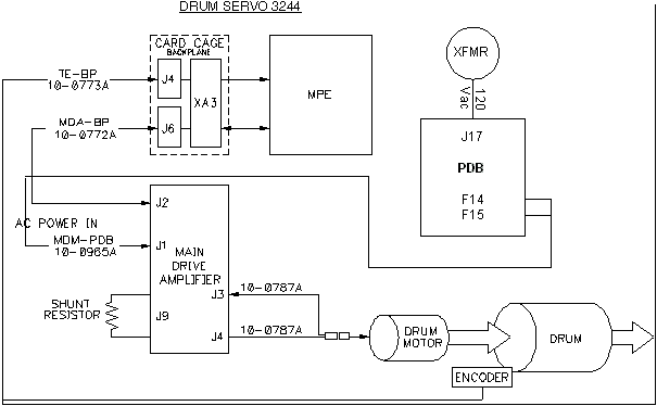
The drum drive amp receives control signals (torque demand) from the MPE firmware and provides controlled power to the drum motor.
A shunt resistor, located above the main drive amplifier (MDA), provides dynamic braking for faster response by dissipating the electricity generated from the kinetic energy of the drum during deceleration.
The drum drive amp is powered by 120V line from the PDB. J15 on the PDB connects to J1 of the amplifier. There are two separate ac lines on the MD-PDB cable. Each line is fused at the PDB. F14 ( 1 amp fast blow ) protects the amplifier logic circuits and F15 ( 8 amp slow blow ) protects the motor drive circuit.
The drum speed is controlled by the MPE firmware via a 5 kHz pulse-width modulated signal into J2 on the drive amp. The duty cycle of this PWM signal is proportional to the output current driven into the motor, which is proportional to the torque generated by the motor. Three Hall effect sensors inside the motor feed back to the drive amp (J3), the motor shaft position, and the drive amp uses these to commutate the power waves (J4) to the motor. The drive amp also feeds back a combined signal from the Hall senseors to the MPE which the MPE uses to initialize the drum, spin the drum in hall mode (drum spin xxc) and as a crosscheck against the speed read from the encoder. The encoder is on the drum and feeds directly into the MPE.
On the PDB (power distribution board) check:
- F14 ( 1 amp 250VAC
rated fast blow ) this fuse protects the drive amp logic board
- F15 ( 8 amp 250VAC
rated slow blow ) this fuse protects the high voltage motor drive circuits.
When power is on you should have 120Vac nominal between pins 1-2 and 3-4 of
J15 on PDB. Note that the drum amp can be permanently damaged if
this voltage is greater than 131Vac. ( If this is the case then replace the
transformer with the one with the lower turns ratio. See ECO B452 for more
details. )
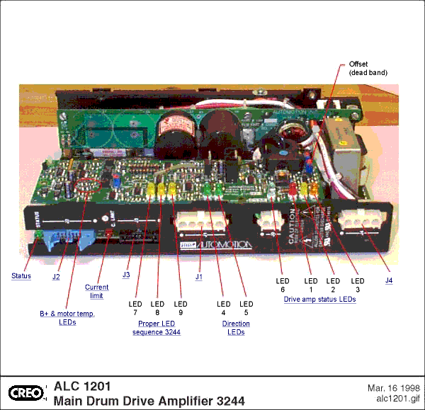
This LED may flicker during high deceleration. If the C Limit LED latches ON with the status LED off, an over current fault has occured. This may be caused by a short in the cable or motor. Open the motor power connector and inspect joints. Measure the motor phase resistance and make sure all 3 phases are more or less balanced. If phase resistance varies by more than 50%, replace motor.
The "drum spin <value> C" command does not require an encoder at all, but it does require the feedback tach signal from the drum drive amp. If this is noisy, it could cause a problem.
The "drum spin <value>" command does not use the Hall effect sensors in the motor to control the speed, but it does compare the speed from the Hall effects to the speed from the encoder, if they differ by more than "maxdiff" (ticks) then an error is generated. The drum amp always uses the Hall effect sensors to commutate the motor fields.
The "drum init" command uses the Hall effect sensors to spin the drum und then checks the encoder, therefore both have to be working.
The "drum torque <value>" command will not work if the encoder does not detect an index pulse once per revolution. It does not require the feedback tach signal from the drum drive amp and does not use the encoder for tracking.
To check the index pulse, type "drum" then turn the drum through one full turn and type "drum" again; the response will tell you if an index has been detected. (The index pulse resets a hardware register in xilinx - DanH.)
If you have drum firmware module version 1.14 or higher, then the drum init checks that the MPE LCA has also received the index - only a problem if using mpelca E 0.03 (type "fw dir" and look for "yes" next to MPELCA E).
Newer drives have a opto coupled isolation board to isolate the Hall effect sensors in the motor from the safety low voltage in the platesetter. See identifying drive amps with the Hall Isolation Board.
| Connector | Description | Cable Name | Number |
| J1 | AC Power In. | MD-PDB | 10-0965A |
| J2 | Control and sensor signals between MPE and MDA | MD-BP | 10-0772A |
| J3 | Sensor input from the drum motor | MDM-MD | 10-0787B |
| J4 | Output signal to the motor stator windings | MDM-MD | 10-3275A? |
| J9 | Shunt Resistor for braking | Drum resistor | 10-3048A |
| Pin | Signal |
| 1 | Logic power (hot) 230 VAC |
| 2 | Logic power (neutral) |
| 3 | Motor power (hot) 200-240 VAC |
| 4 | Motor power (neutral) |
| 5 | GND |
| Pin | MPE Signal | MDA Signal | Purpose |
| 1, 2 | +5 V | +5 V (input) | Logic supply for isolated I/O drivers |
| 3 | MD.ENBL | ENABLE (input) | Enables MDA output to motor |
| 4 | Reserved | ||
| 5 | MD.REV | REVERSE (input) | Changes motor direction |
| 6 | MD.BRAKE | BRAKE (input) | Enables dynamic braking |
| 7 | MD.FAULT | ENABLED (output) | Low during fault condition |
| 8 | MD.TACH | TACH (output) | Tach signal from motor sensors to MPE |
| 9, 10 | GND | GND | Return/common for control logic |
| 11 | MD.C PWM | CURRENT PWM (input) | Drive to motor PWM circuit |
| 12 | MD.AN+ | DIFF CURR. + (input) | Differential analog current drive input + |
| 13 | MD.AN- | DIFF CURR - (input) | Differential analog current drive input - |
| 14 | MD.CURR | CURRENT SIG. (output) | Proportional to output current |
| No Hall Isolation Board | With Hall Isolation Board | ||
| Pin | Signal | Pin | Signal |
| 1 | +15 V power out to Hall sensors | 1 | +5V power out to Hall sensors |
| 2 | S1Hall sensor input | 2 | S1Hall sensor input |
| 3 | S2Hall sensor input | 3 | S2Hall sensor input |
| 4 | S3Hall sensor input | 4 | S3Hall sensor input |
| 5 | Hall common return | 5 | Hall common return |
| 6 | Jumper to pin 7 | 6 | Jumper to pin 7 |
| 7 | Jumper to pin 6 | 7 | Jumper to pin 6 |
| 8 | Reserved | 8 | +5V ISO Hall power input (PS 1) |
| 9 | Reserved | 9 | ground (not used) |
| 10 | Reserved | 10 | common Hall power input (PS1) |
| Pin | Signal |
| 1 | Motor ground |
| 2 | Phase output |
| 3 | Phase output |
| 4 | Phase output |
| Pin | Signal |
| 1 | Shunt high |
| 2 | Shunt low |
| LED | Color | Indication |
| Status | Green | MDA operational and enabled |
| Current Limit | Red | Sourcing near maximum peak current (variable intensity) |
| 1 | Red | Overcurrent fault (latched condition) |
| 2 | Yellow | Current foldback/ attention |
| 3 | Orange | Current command (variable intensity) |
| 4 | Green | Direction toggle |
| 5 | Green | Direction toggle |
| 6 | Green | Logic power OK |
| 7 | Yellow | Hall S1(see Note below) |
| 8 | Yellow | Hall S2(see Note below) |
| 9 | Yellow | Hall S3(see Note below) |
| Motor overtemp | Red | Over temperature
LED is located behind J2 |
| Over voltage | Yellow | B+ voltage high
LED is located behind J2 |
Note: LED 7,8 and 9 can be on at the same time but they should toggle
as follows (3244 engines only).
For 3244 engines (with Bodine motors and ALC 1201 drive amps), Hall effect
commutation sensors are 60 degrees apart.
| "Forward Motion" | ||
| LED7 | LED8 | LED9 |
| S3 | S2 | S1 |
| 0 | 0 | 0 |
| 0 | 0 | 1 |
| 0 | 1 | 1 |
| 1 | 1 | 1 |
| 1 | 1 | 0 |
| 1 | 0 | 0 |
There are two invalid states:
| Invalid states, forward Motion | ||
| LED7 | LED8 | LED9 |
| 0 | 1 | 0 |
| 1 | 0 | 1 |
If either invalid state is detected on older drive amps then a fault is generated (shows up as error 06011 or error 12008). If the drum is rotated slowly by hand, each yellow LED should change state at least once within a motor revolution.
If one of the LEDs appears frozen, see 3244 Hall Sensor Problems.