Home | Contact Us | Submit Troubleshooting Info | Search | Help
Output | Software Solutions | Proofing | Color, Screening and Calibration | Scanning | Digital Photography | Consumables | POS
Home | Contact Us | Submit Troubleshooting Info | Search | Help
Output | Software Solutions | Proofing | Color, Screening and Calibration | Scanning | Digital Photography | Consumables | POS
Note: Check SAP for latest BOMs.
Air SupplyDebris Removal
Engine
Engine module
Exposure heads
Fan box
Load ramp
Panels
Power box
Trendsetter 3244—02-4154
Drawing not available | BOM
Fly-off sensor
Transmitter—36-3117
Receiver—36-3118
Cable assembly—10-3612A
Air Supply Filter/Regulator—55-0318
Air Filter Regulator Assembly Photo
Particulate filter—55-0324
Replacement bowl—55-0690Coalescent filter—55-0325
Replacement bowl—55-0690Adsorption filter—55-0326
Replacement bowl—55-0694
For pneumatic parts, see Manifold
Bore/flextube adapter kit—50-1242
Drawing| BOM
Note: Item #30 is an M6*10 set screw, 52-4116, used to secure the
collar added to each end of the carriage.
Item #70 is an M6*16 screw, 52-4226, that is the only screw that secures the
flex tube to the carriage. It is screwed in flush with the carriage and aligns
with a hole in the flex tube and the collar.
Carriage motor assembly—11-0403
Drawing
Carriage drive belt—54-3256
TS3 water cooling kit (hoses and cables)—11-0588 includes:
Trendsetter water cooling kit (hoses and cables)—11-0805
Uses an external chiller to water-cool the head
Drawing | BOM
See External Chiller for more details.
Note: The external chiller is no longer available.
CRS TS3 and TS3/8 devices use a Heat exchanger.
DHU System—50-2442
BOM
TS3/8 Engine—50-1728
Drawing | BOM
Ballscrew hanger UE—50-1620
Drawing| BOM
You must replace entire assembly #50-1620 since the bearing cannot easily be removed from the hanger.Cable TEE(J20) to valve—10-4066
Drawing| BOMCarriage motor mount—50-1623
Drawing not available | BOMClamp cylinder drive (away) end —50-1659
Drawing| BOMClamp cylinder encoder (home) end—50-1658
Drawing| BOMDrum motor—50-1071
Drawing| BOMDrum motor timing belt—54-3894
EAUM-Mech hazards relay—10-4070
Drawing| BOMFrame/track—50-1682
Drawing not available | BOMEngine frame, 1586*377*501—57-5253
| BOMFilm le guide—50-1463
Drawing| BOMEncoder assembly—507-00165A (replaces 32-4130A - Jul 2004)
Drawing | BOMLeading edge actuator (backbone)—50-1087
Drawing| BOM(If low profile clamps have been installed)
LE Clamp, low profile with dowel pin installed—500-03322A
Pivot block kit—512-00260A
kit includes long (57-6851B) and short (57-7698B) pivot blocks(If high profile clamps have been installed, no UDRC)
Leading edge clamp assembly—50-1212A
For drawing see item 740 on engine Drawingclamp body—57-2076
dowel—52-4343
pivot body, central—57-4772A
pivot body, ends—57-2077BLoad unload control panel—50-1096
Drawing| BOMManifold, solenoid valve—50-1649
Drawing not available | BOMReplacement solenoid valve gasket—316-00003
photo of solenoid and gasketNorth magnetic clamp—50-1091
Drawing| BOMPlate exit door—50-1299
Drawing| BOMRoller CTP—50-1089
Drawing| BOMSouth magnetic clamp—50-1131
Drawing| BOMTrailing edge actuator (backbone)—50-1898
Drawing| BOMTE Clamp Actuator Backbone—57-2104
Drawing | BOM not availableMicroswitch—15-3478
Microswitch bracket—57-8893A
TEC lock/unlock cylinder—55-0065
TEC lock/unlock cylinder—55-1210 (TS3/8 devices with S/N S332-S387 and S983631001-S993631323 devices with FCO CA03931 completed)
TEC optical sensor—36-3210
Engine module—50-1300
Drawing| BOM
Frame—50-1366
Drawing not available | BOM
Upgrade Kit, TS# to TS3244V or TS3244X—02-4314
Drawing not available | BOM
Exposure head 2400 dpi, thermal—32-4005
Drawing not available | BOM
Exposure head 3200 dpi, thermal—32-4030
Drawing not available | BOM
Exposure head 2400 dpi, 48V, fast TEH 1.7—32-4141
Fan box—11-0441
Wiring Diagram | BOM
Fan box wiring tray—11-0542
Drawing| BOMAir Supply Filter/Regulator—55-0318
Photo | BOMReplacement bowls and drain:
Black bowl/guard, no drain 55-0693
Black bowl/guard, manual drain 55-0694
Black bowl/guard, Auto drain, low flow 55-0690
Trendsetter EM Kit—11-0560
Assembly Drawing | BOM
Cylinder, lower ramp—50-1653A
DrawingGlass load ramp—57-6166
Drawing| BOM not availablePlate alignment assembly—50-1298
ECO D023 (for machines with 100 label 24)
Drawing| BOMPlate alignment—50-1298
(for machines with 100 label 23)
Drawing not available | BOM
Wire rack kit—50-1838
Drawing not available | BOM
Wire load ramp—57-6062
Drawing|Wire rack left bracket—57-6174
Drawing
Panels kit—50-1301
Drawing| BOM
Gas strut (cylinder) that supports front door—55-0564
Metal FAB panels TS3—50-1433
Drawing not available | BOM
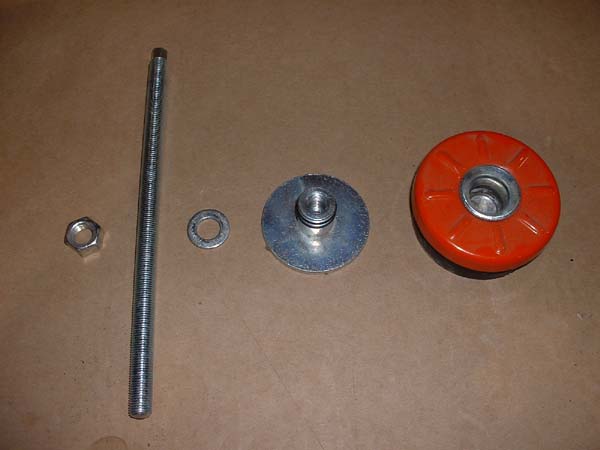
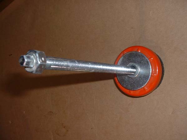
Leveling feet—59-3295A
Drawing | Photo of parts | Photo of assembly
Encoder adapter cable—10-4065
Drawing| BOMFlex track—10-3209
Drawing, Page 1, page 2| BOMKeyswitch SIO, Powerbox TS—11-0556
Drawing not available | BOMMechanical Hazards Relay—10-4067
Drawing| BOMMain drive amp/Servoamp—15-3330
Power Supplies
PS1 through PS6