Home | Contact Us | Submit Troubleshooting Info | Search | Help
Output | Software Solutions | Proofing | Color, Screening and Calibration | Scanning | Digital Photography | Consumables | POS
Home | Contact Us | Submit Troubleshooting Info | Search | Help
Output | Software Solutions | Proofing | Color, Screening and Calibration | Scanning | Digital Photography | Consumables | POS
Important: Only a trained specialist should perform these installations.
This document describes the installation and calibration of the punch system.
The installation includes two stages :
The calibration is performed along the width and height axis referred to the punch center holes on each axis.
- Bar punch according to the customer order
- Punch cutouts collector tray
- Bow for bar punch
- Move the carriage to E.P (End Position) and disassemble the Bow by removing the 4 screws that hold it (you will use these screws later to assemble the new bow).
- Move the carriage back in order to release the Bow.
In VER. 5.10 there is a bug that doesn’t allow you to move the carriage to the EP unless there is a film in the drum.
- The plug is attached to the drum by 3 supports.
- Under the 3 supports there might be some spacers.
- Verify that they will not fall.
- Put the Plug with the spacers, screws ‘old’ bow and inside the plotter. ?
- Insert the Bar Punch from the right side of the Imagesetter (The EP Side ), by putting it first on the right punch support and slipping it gently into the punch hole in the drum.
- Rest the punch on the two Bar punch supports (you may need to move the carriage manually a little bit to the right in order to enable the punch to get into the hole).
- Attach the Bar punch to the supports using 3 10-32 screws (two regular on the right side of the punch and one with shoulders on the left side).
- Make sure that the punch is attached (but not fully tightened) to the support on both surfaces.
- Make sure that the punch will not touch the drum. ( Move a piece of film between the punch and the drum in order to check the space between the punch and the drum. Use small pieces of film to change the punch position if necessary.
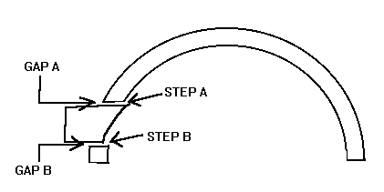
- Check with a piece of film the two steps described in fig 1 (A & B below). You can do it by entering the film from the drum side and following the steps. Step ‘B’ is not critical since the film does not usually not reaching this point.
- Check that the piece of film is moving smoothly from the loading cassette side to the drum (regular film direction).
- Check film loading and make sure that the film does not collide with the punch. Manually advance full width of the film.
Figure 1
- Assemble the flag using 4-40 screw.
- Assemble the detector on the left side of the punch.
- Connect the detector wiring (open the cord and find the cable with ‘P- board’ label on it).
M. Board assembling
- The punch M-Board is assembled on a special plate that attached to the left plunge (like in Fig 2).
- If a side punch system is installed the M-Board is attached to the punch vacuum pump holder.
Figure 3
- Service util / Machine / Punches / Set active, set 0 ‘YES’ and press ‘Done’
- Service util / Machine / Punches / Run
(This List does not refer to Punch Master 2).
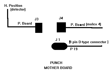
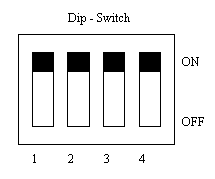
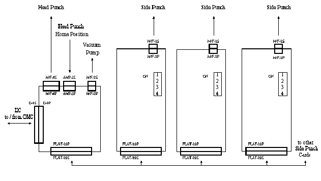
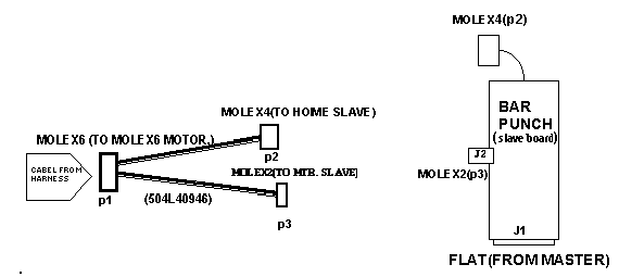
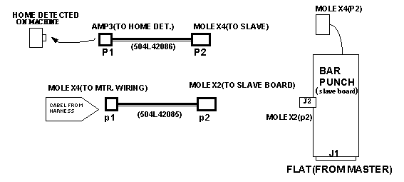
The machine has two kinds of wiring, molex6-pin or molex4-pin. The wiring kit contains two kinds of adapters to connect the bar punch slave board - please refer to the wiring description above.
The slave board cat. # is 503A38329 .
* choke should be connected near the motor.
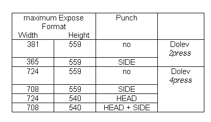
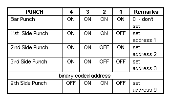
Attention: Head punch address is always zero.
Set the punch format the offsets to :
Head Punch - ML - W=30 H=0
Side Punch - TC - W=0 H=30
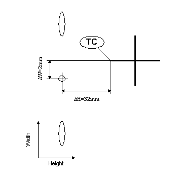
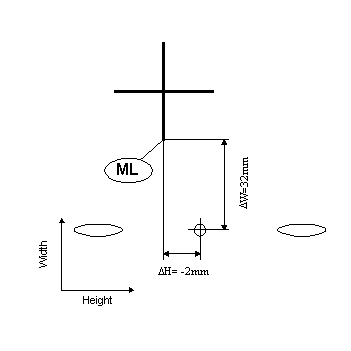
If the distance is bigger / smaller then the Offset From Pivot reduce / enlarge the pivot HEIGHT and / or WIDTH accordingly.
Punch System Option – Installation (1)
In the above figure the difference between the desired and actual measurement is +2 mm, therefore the PIVOT HEIGHT / WIDTH should be changed by -2 mm .
Punch System Option – Installation (2)
In the above figure the difference between the desired and actual measurement is -2 mm in the HEIGHT , therefore the PIVOT HEIGHT should be changed by +2 mm .
In the above figure the difference between the desired and actual measurement is +2 mm in the WIDTH , therefore the PIVOT WIDTH should be changed by -2 mm .
Remark: Change the PIVOT HEIGHT / WIDTH in the punch settings utilities. Don't forget to GET PLOTTER PARAMETERS
Calibration Procedure - Alignment
Orientation (only)
Click to see the full size

 Click to see the full size
 Click to see the full size
 Click to see the full size