|
Product
|
|
- ThermoFlex® Mid
- ThermoFlex Narrow
|
|
Component |
|
One of the following may be faulty:
- TSP cable
- Light detector
- DDB board
- LDD board
- TSP board
- Diode
|
|
Symptoms
|
|
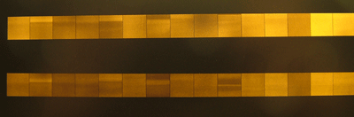
Patterns, artifacts, lines, stripes, or streaks appear on the image,
as shown, during laser uniformity calibration testing.
|
|
Cause
|
|
- TSP cable connection is loose
- Calibration of one of the following is incorrect:
- focus
- elevation
- intensity
- The connections of one of the following boards are faulty:
- Light detector parameter values are incorrect
- TSP cable is defective
- Light detector is defective
- One of the following boards is faulty:
- Diode(s) malfunction
|
|
Solution
|
|
After each step, expose an image to check whether the change has resolved
the problem.
- Verify that the TSP cable is firmly connected, and fix if required.
- Perform the following calibration test procedures:
- Remove the DDB board, clean its connections, and return the board
to its place.
- Repeat step 3 for the LDD and TSP boards.
- Check light detector parameter values:
- Check what factor appears on the light detector.
- In the hardware tree, select ...IO OBJECTS > LOCAL 3 >
LDT > Light Detector and verify that the High and
Low Dac Factor parameter values match the factor that appears
on the light detector.
- In the Laser Group dialog box, verify that the laser calibration
value is 600 mw.
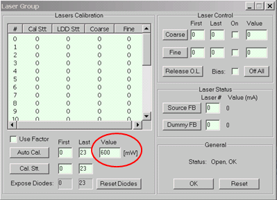
- Verify that the coarse factor is 130 ±20 and that
the laser log is 950 ±150.
- If the coarse factor is not within this range, increase or decrease
the light detector factor as required.
- Replace the light detector (see Light Detector Replacement procedure).
- Replace the TSP cable.
- Replace the DDB board.
Note: If this resolves the problem, perform the Delay Calibration Test.
- Replace the LDD board.
- Replace the TSP board.
- Check which diode or diodes produce the patterns and replace the relevant
diodes.
Note: If this resolves the problem, perform the Resolution Calibration Test
and the Drum speed calibration test (for flexo plates).
|
|
Technical contact(s)
|
|
Viki Arviv
|
Date submitted
|
|
08 Aug 2004
|

