| |
This procedure includes the following sections:
Before you begin
- On the Magnus 400 Controller desktop, double-click the
MachineBackup icon to save the registry and database files. See
Saving the Registry and Database Files in the Magnus
400 Controller 1.05.394 Cold Start Software Installation Guide (731-01206A).
Note: For Magnus 400 II Quantum platesetter configurations
with thermal 2 heads (TH2), in addition to saving the registry and
database files, you must also save the NVS parameters. See Saving and restoring NVS parameters on a Magnus 400 Quantum platesetter.
- In the Magnus 400 Controller software, on the Operations toolbar,
verify that Ready appears in the platesetter status indicator.
- Open the front, rear and right-side doors of the platesetter.
- Quit the Magnus 400 Controller software, Service Shell, and any other
software that might be open.
Removing parts and assemblies
- Before you remove any parts or assemblies from the platesetter, verify
that the platesetter is leveled properly on all four legs. See the relevant
Magnus 400 II or Magnus 400 II Quantum
hardware installation guide.
- Shut down the Magnus 400 II system:
- Turn off the platesetter.
- Disconnect the platesetter from the main power supply.
- Turn off the air supply.
Removing the front panel and the loading tray
- Remove the two screws that secure the front panel to the mainframe,
and remove the front panel. Set the front panel screws aside.
- At the front of the platesetter, remove the loading tray harness from
the loading-tray support brackets.
- On the right loading-tray support bracket, disconnect the Molex®
connector.

- Remove the two spring screws located on the top part of the tray,
near the platesetter mainframe.
- On each suppport bracket, remove the two hex screws that secure the
support bracket to the loading tray, and remove the tray. Set the screws
aside.

- Under the loading-tray support brackets, on each support bracket,
remove the two head screws that secure the loading-tray support brackets
to the mainframe, and remove the brackets. Set the screws aside.
Removing the front door
Warning: The front door is very heavy. Two
people are required to remove the front door.
- Remove the nine screws that secure the front door to the mainframe
(four on the left side, four on the right side, and one in the center).
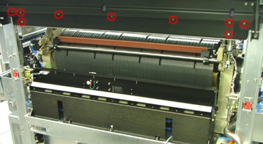
- Loosen, but do not remove the two screws that secure the front-door
support pistons to the mainframe. Slide the door up to remove it.

- Remove the two screws that secure the front-door support pistons to
the mainframe, and set the screws aside.
Removing the plate driver assembly, interlocks, and lockers
Attention: Before you proceed, verify that
the air supply to the platesetter is turned off.
- On the plate driver assembly, disconnect the Molex®
harness connector (labeled LOADING) from the platesetter.

- Disassemble the plate driver assembly:
- Remove the seven screws (two on the left side, two on the right
side, and three in the center) that secure the plate driver assembly
to the mainframe.
- Lift up the plate driver assembly, and disconnect
the two air pipes from the cylinder.
- Remove the plate driver assembly.
- Verify that air does not escape during operation. Fold the edges of
the air pipes that you disconnected (in step 2b),
and close the adjusting screw in the manifold.
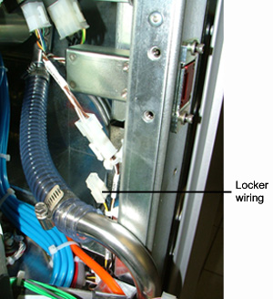
- Remove the left- and right-side door lockers.
- On the front-left side of the platesetter, coil the wiring and attach
it to the harness.

- On the right side of the platesetter, leave the locker wiring loose
(so that you can connect it later to the MCU II).
Installing parts and assemblies
Assembling the light guard and location pin
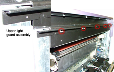
- Attach the new upper light guard to the mainframe with the top part
of it hanging over the screws, and tighten the screws in the five existing
holes.
- Assemble the location pin together with the left- and right-pin base.

(Optional) Replacing the drum vacuum adapter
Note: The following procedure is for Magnus 400 family configurations
only.
- On the right side of the platesetter, remove the existing drum vacuum
hose adapter.

- Install the longer drum vacuum hose adapter (from the kit), and secure
it in place on both sides of the adapter with cable ties.

Assembling the punch and centering system
- Connect the punch beam adapters to the left and right sides of the
platesetter:

- Attach the left punch beam adapter with two conical head
screws, and tighten both screws.
- Attach the right punch beam adapter with three conical
head screws, and tighten all three screws.
- Place the punch and centering beam on top of the spacers, with the
chain facing the front.
- Insert the three punch bar screws, but do not tighten the screws:
- On the left, insert two punch bar screws.
- On the right, insert one punch bar screw.
- Measure the distance between the punch and centering system and the
optomech assembly on the left and right sides. The distance should be
the same on both sides, with a tolerance of ±0.5 mm (0.02 in.).
Adjust if required.
Note: The holes are large enough to swivel and adjust the
punch so that it is parallel to the drum.
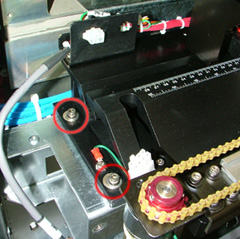
- When the punch and centering system are correctly positioned, tighten
the three punch beam screws (two on the left side, and one on the right
side).
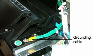
- On the right side of the punch beam, connect the green grounding cable
to the punch beam.
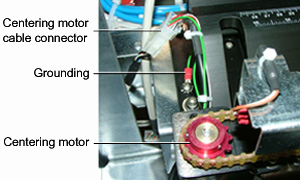
- Connect the centering motor cable to the centering motor cable connector,
and the grounding to a screw on the punch beam.
Installing punches
To install punches, see Installing punches.
Connecting the MCU II to the platesetter
To connect the upgraded MCU II to the platesetter, see Installing
the MCU II-Ready to the Platesetter in the MCU II/SCU II Installation and Upgrade Guide.
Connecting the air pressure pipe
- Plug one end of the air pressure pipe into the air pressure outlet
in the wall.
- Cut an 8-cm (3.15-in.) piece of air pipe.
- On the rear-right side of the platesetter, attach one end of the 8-cm
(3.15-in.) air pipe to the main air pressure outlet.

- Connect the other end of the 8-cm (3.15-in.) piece of air pipe to
a Y connector.
- Connect a long piece of air pipe to the other side of the outlet on
the Y connector, and route the air pipe toward the front of the platesetter.
Upgrading the Magnus 400 Controller software for
MCU II or SCU II
The procedures in the following section describe how to install and upgrade
the Magnus 400 Controller software on Magnus 400/Magnus 400 II LDA and
Quantum platesetter configurations.
Installing the software on LDA platesetter configurations
- Insert the latest Magnus 400 Controller software CD into the CD-ROM
drive. When the Closing Application Warning dialog box appears, verify
that all software is closed, and click Continue Setup.

- When the Welcome Maint dialog box appears, select Install,
and click Next.
- When the Magnus Family Installation Setup dialog box appears, click
Next.
The Customer Information screen appears.
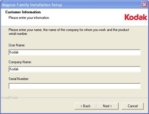
- Type the following customer information, and click Next.
- User Name: Kodak (or customer's name)
- Company Name: Kodak (or customer's name)
- Serial Number: (the Magnus 400/Magnus 400 II platesetter serial
number)
The Machine Type dialog box appears.
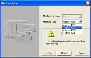
- Perform the following steps:
- The Machine Revision list is predefined and cannot be changed.
- In the Machine Type list, select the platesetter configuration
that you are installing.
- Click Next.
The Machine Type dialog box is refreshed, and the selected platesetter
type appears in the title bar.
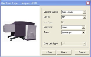
- Perform the following steps:
- In the Loading System list, select Auto Loader.
- In the UDRC list, select either None, BP,
or Other.
Note: If you select BP, verify that the UDRC BP cable
and the nozzle vacuum detector and wiring are installed on the
platesetter.
- The Xpo Open check box is predefined and cannot be changed.
- In the Conveyor list, select either none or Standard.
- In the Trays list, select three trays (for MCU II)
or one tray (for SCU II).
- In the Data Unit Type list, LIF is predefined and
cannot be changed.
- Click Next.
A progress indicator appears, and the following message appears.

- Click OK.
The Magnus 400 Controller software takes a few minutes to load.
After the software is successfully installed, the Reboot screen appears.

- Remove the Magnus 400 Controller software CD from the CD-ROM drive,
and close all open platesetter doors.
- Select Yes, I want to restart my computer now, and click Finish.
- Install the Xpo 3.2 software. See Downloads
on the Xpo for Magnus 400/Lotem 400 Xpose site on TechPlanet.
Important: Do not start the Magnus 400
Controller software until you verify that the correct firmware versions
are installed.
Verifying firmware versions for LDA platesetter configurations
Note: To use Kodak Service Shell, you must insert a service dongle.
- On the Magnus 400 Controller desktop, double-click the Service
Shell Client icon.
- In the Connection Dialog dialog box, click Connect.
The Service Shell workspace appears.
- On the left panel in the Service Shell workspace, click Device
Monitor.
- At the
LMCE>> command prompt, type fw dir,
and press Enter.
For platesetters with an LDA head (LMCE firmware), the following
application versions should appear:
MCE_MAIN: 1.04.01MCE_LCA: 70.89MCE_BOOT: 1.16.01MCE_POST: 1.06
- Quit the Service Shell workspace, and start the Magnus 400 Controller
software.
- If you do not have the correct firmware versions installed, see Installing
Firmware Version Files in the Magnus
400 Controller 1.05.394 Cold Start Software Installation Guide (731-01206A).
- Verify that the values for the plate-loading and paper disposal parameters
that are configured on the platesetter are within the minimum-maximum
range for these parameters. See the MCU/MCU II Loading System Parameters
in the MCU II
Plate Loading Sequence and Parameters Guide for Magnus 400 II Family Platesetters.
- Start the Xpo software. Verify that the correct version is installed
on the platesetter, and perform reconfig:
- On the desktop, select Start > Programs > Xpo, and
double-click Config.
- In the Parameters dialog box, select Local Host, and click
Next.
- In the Results dialog box, click Next.
- IN the Screen Board dialog box, click Finish.
Defining punches
If you installed punches on your upgraded configuration, you need to
define the punches in the Magnus 400 Controller software. See Defining
Punches in Installing punches.
Testing the LDA platesetter with MCU II configuration
To test the upgraded configuration, see Testing the Magnus 400 II/Magnus
400 II Quantum With MCU II Configuration in the MCU
II/SCU II Installation and Upgrade Guide.
Installing the software on Quantum platesetter configurations
- Insert the latest Magnus 400 Controller software CD into the
CD-ROM drive. When the Closing Application Warning dialog box appears,
verify that all software is closed, and click Continue Setup.
- When the Welcome Maint dialog box appears, select Install,
and click Next.
- When the Magnus Family Installation Setup dialog box appears, click
Next.
The Customer Information screen appears.
- Type the following customer information, and click Next.
- User Name: Kodak (or customer's name)
- Company Name: Kodak (or customer's name)
- Serial Number: (the Magnus 400 Quantum/Magnus 400 II Quantum platesetter
serial number)
The Machine Type dialog box appears.

- Perform the following steps:
- The Machine Revision list is predefined and cannot be changed.
- In the Machine Type list, select the platesetter configuration
that you are installing.
- Click Next.
The Machine Type dialog box is refreshed, and the selected platesetter
type appears in the title bar.

- Perform the following steps:
- In the Loading System list, select Auto Loader.
- In the UDRC list, select either None, BP,
or Other.
Note: If you select BP, verify that the UDRC BP cable
and the nozzle vacuum detector and wiring are installed on the
platesetter.
- In the TH Config list, select either 2400 or 2540.
- In the Conveyor list, select either none or Standard.
- In the Trays list, select three trays (for MCU II)
or one tray (for SCU II).
- Click Next.
The Magnus 400 Controller software takes a few minutes to load.
After the software is successfully installed, the Reboot screen appears.
- Remove the Magnus 400 Controller software CD from the CD-ROM drive,
and close all open platesetter doors.
- Select Yes, I want to restart my computer now, and click Finish.
Important: Do not start the Magnus 400
Controller software until you verify that the correct firmware versions
are installed.
Verifying firmware versions for Quantum platesetter configurations
Note: To use Kodak Service Shell, you must insert a service dongle.
- On the Magnus 400 Controller workstation desktop, double-click the
Service Shell Client icon.
- In the Connection Dialog dialog box, click Connect.
The Service Shell workspace appears.
- On the left panel in the Service Shell workspace, click Device
Monitor.
- At the
Quantum>> command prompt, type fw
dir, and press Enter.
For platesetters with a thermal 2 imaging head (TMCE firmware), the
following application versions should appear:
MCE_MAIN: 1.04.02MCE_LCA: 2.28MCE_BOOT: 1.16.1MCE_POST: 1.06
- To view the thermal 2 imaging head application version, at the
Quantum>>
command prompt, type th2 "ver.
The following application version should appear: TH2: 1.05d
Release
- Quit the Service Shell workspace, and start the Magnus 400 Controller
software.
- If you do not have the correct firmware versions installed, see Installing
Firmware Version Files in the Magnus
400 Controller 1.05.394 Cold Start Software Installation Guide (731-01206A).
- Verify that the values for the plate-loading and paper disposal parameters
that are configured on the platesetter are within the minimum-maximum
range for these parameters. See the MCU/MCU II Loading System Parameters
in the MCU
II Plate Loading Sequence and Parameters Guide for Magnus 400 II Family
Platesetters.
Defining punches
If you installed punches on your upgraded configuration, you need to
define the punches in the Magnus 400 Controller software. See Defining
Punches in Installing punches.
Testing the Quantum platesetter with MCU II configuration
To test the upgraded configuration, see Testing the Magnus 400 II/Magnus
400 II Quantum With MCU II Configuration in the MCU
II/SCU II Installation and Upgrade Guide.
|

