Home | Contact Us | Submit Troubleshooting Info | Search | Help
Output | Software Solutions | Proofing | Color, Screening and Calibration | Scanning | Digital Photography | Consumables | POS
Home | Contact Us | Submit Troubleshooting Info | Search | Help
Output | Software Solutions | Proofing | Color, Screening and Calibration | Scanning | Digital Photography | Consumables | POS
Before installing the skins, rear access guards, and guard rail:
 Move the picker to a position in the middle of the table.
Check that the AC power is OFF.
Complete the picker assembly.
- Remove the brass weight from the picker.
- Install the main picker skin.
Rotate the top in first, then swing the bottom in until the skin falls into place.WARNING! Be careful not to jolt or make contact with any picker components.
- Install the small top picker skin - there are two clips on the back of the picker that hold it in place.
Complete the track assembly.
- Connect the track light inside the end skin.
- Maneuver the end skin over the end track flange.
Lower the outside end first so that the plastic lip fits in under the track.- Install the 6 fasteners loosely.
- Repeat (a) to (c) for the other end skin.
- Place the center skin on the track and end skins.
- Snap the front edge of the center skin over the end skins.
- Install the 4 fasteners loosely.
- Tighten all 10 skin fasteners.
Check the movement of the picker.
- Move the picker along the entire length of the track by pulling or pushing the drive belt.
Movement should be smooth and easy, with no mechanical contact or interference.
Install the table finger guard. This component may already be installed.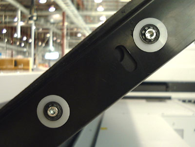 Finger guard push-nuts
Install the guard rail.
- Open the p-door and raise the table.
- Remove the two front panels from the Trendsetter VLF.
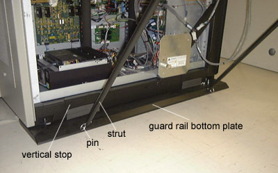
- Slide the lower support panels under the front bottom edge of the machine until the vertical stops butt up against the machine. (When the front panels are replaced, their pressure will hold the plate firmly in place.)
Lower support panel in position
- Assemble the guard rails. Note: Your guard rails may already be partially assembled.
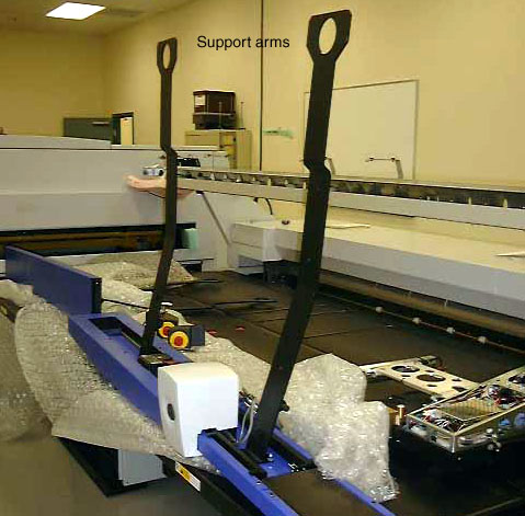
- Lay the rails upside down on bubble plastic.
- Attach the support arms to the inside of the rails using four screws. Do not tighten them yet.
Attaching the support arms
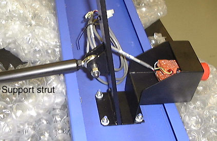
- Attach the emergency stop switches to the rails using the same screws as for the support arms.
The switch with the two plugs goes on the right hand side of the machine.- Tighten the screws holding the support arms and emergency switches in place.
- Attach the support struts to each support arm.
Attaching the support struts and emergency stop switches
- With a helper, hold each guard rail assembly in place.
- Position the struts onto the locating pins on the bottom plate.
- Fasten the support arms on the top of the VLF TS.
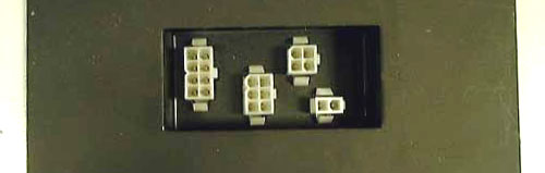
- Connect the two cables from the right-hand guard rail assembly to the receptacle on the top surface of the VLF TS. Use cable ties to attach the cables to the underside of the support arm (pay attention to where the guard rail gate slides open so that the cables will not be damaged by the gate).
Emergency stop switch to VLF TS receptacles
- Connect the cable from the left emergency stop switch to the connector located near the filter regulator assembly. Use cable ties to hold the cable to underside of the support arm and route the cable through the hole in the top of the VLF TS.
- Install the cover bracket and the cover plate over the cables.
- Align the sliding gate with the rail.
To adjust the gate-rail height:
- Rotate the bottom support rods until the sliding gate and rail are aligned - clockwise goes up and anti-clockwise goes down.
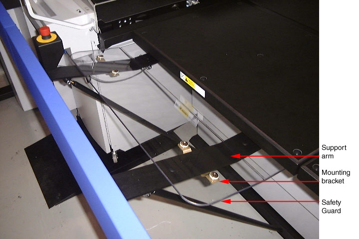
- Install the front guards.
There are two guards that cover the openings between the table and guard rails - one on each side of the guard rail gate.
- Remove the protective cover from the guard.
- Lay the guard on top of the guard rail support arms so that the contours match.
- Hold a bracket on the underside of a support arm and insert the screws with plastic washers from the top (there are two brackets per guard).
Front safety guard
- Repeat to attach the guard on the other side.
- Install the gate safety bar. Note: The gate safety bar may already be mounted to the gate.
The gate safety bar mounts to the back of the guard rail gate with the bend pointing downwards.
- Remove two screws on each end of the gate to mount the gate safety bar brackets.
Viewed from the front, the right side bracket mounts horizontally and the left side bracket mounts vertically (the picture below is viewed from behind).- Attach the gate safety bar and tighten the screws.
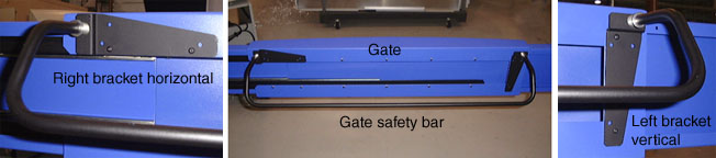
- Insert the four retaining pins.
- Tighten all fasteners.
- Lower the table.
- Close the p-door.
- Close the guard rail gate.
Drawing: Installed rail assembly
Install all the Trendsetter VLF outer panels.
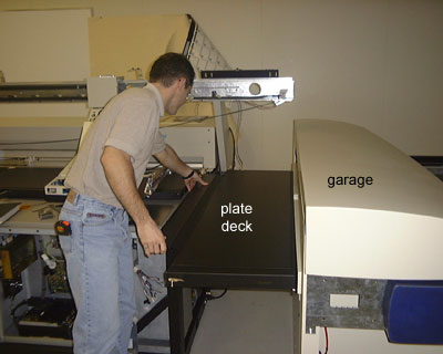
If slipsheet removal is not being installed, install the plate deck.
- Position the plate deck between the machine and the garage.
The wide end sits on the bracket on the face of the garage. The narrow end sits on the top frame of the Trendsetter VLF. (There are no screws or fasteners.)
Installing the plate deck
Install the rear access panels.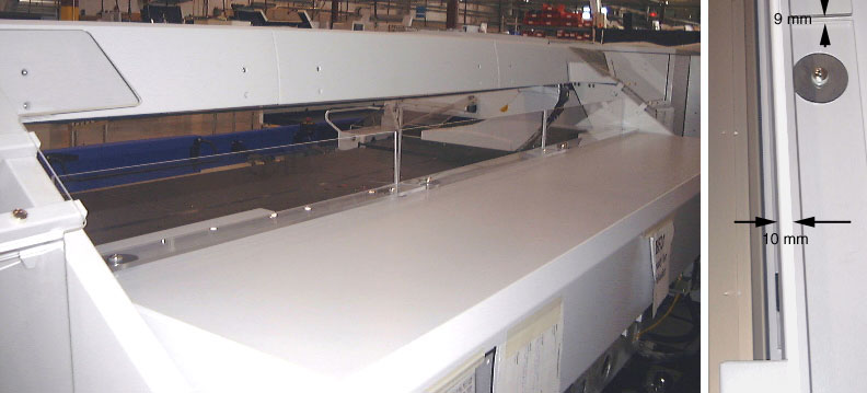 Installing
the hood guards
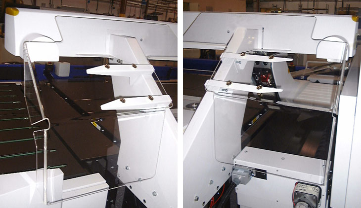 Installing
the side guards
Warning! Before opening the hood, remove both side access guards and the hood access guard that is directly behind the picker.