Dolev 4press - Assemblies
Loading/Unloading System
Detectors
Film loading and unloading is performed using three (3) detectors:
| |
Location and Description |
| Film In Detector |
At front left of Imagesetter, below drum. Detects entry of
film into the Imagesetter from the Loading Cassette. |
| Film Out Detector |
At rear right of Imagesetter, below drum. Detects exit of
film from the Imagesetter drum. |
| Accumulating Cassette Detector |
On right side of Accumulating Cassette. Detects entry of
film into the Accumulating Cassette. |
Film Loading/Unloading Steps
Loading and unloading steps are performed in a set sequence, during
which time standard status messages are displayed on the control monitor. These status
messages keep the Operator informed as to the exact state of the process, and can be used
to isolate film loading or unloading problems.
| First Advance |
Initially loads film from loading cassette into
Imagesetter drum. |
| Advance |
Moves the film along film path toward the accumulating
cassette or the inline processor. During a regular advance, both loading and unloading
motors are active, as are the Accumulative Cassette or Conveyor motors. |
| Attach |
Loading and unloading motors are activated to create the
proper film tension in the Imagesetter drum. |
| Expose |
Film resides in Imagesetter drum. The exposure process is
performed. |
| Relief |
The opposite of Attach. Loading and unloading motors are
activated to relieve film tension in the Imagesetter drum. |
| Cut and Collect |
An Advance is performed to move exposed film fully out of
the drum. The cutter motor is activated to perform a film cut. Film is then
collected:Accumulating Cassette. The accumulating cassette motor is used to pull exposed
film into the Accumulating Cassette. When film collection is complete, the Unloading
Drawer opens.Inline Processor. The Conveyor motor is used to pull exposed film into the
processor. |
| Empty Drum |
The Imagesetter is cleared of all film. Film currently
residing in the drum is moved back into the Loading Cassette, and the Loading Drawer
opens. |
Film Loading Sequence
- The Loading Cassette is placed in the Imagesetter. The film is
trimmed and the Loading Drawer is closed.
When the Loading Drawer is closed, the loading rollers inside the Imagesetter are engaged
to receive the new film.
- The control monitor displays the Media Information table, which
stores Loading Cassette memory information. If necessary, the current parameters are
entered.
The Dynamic Optics Carriage is moved to the center of the film. (The centering calculation
is determined from Film Width parameter in the Media Information table.) The film bow is
used to deflect the film during film first loading.
- A First Load is performed and film is advanced through the film
rollers. Both Load and Take motors are activated to advance the film from the Loading
Cassette completely into the Imagesetter drum.
- An Attach is performed to apply the required tension to the film
inside the drum. This is accomplished by reversing the Take motor slightly, while
advancing the Load motor. The two motors then work against each other to create the proper
film tension. (Tension is maintained throughout the exposure process by keeping both Load
and Take motors activated.)
- Exposure takes place. During exposure, film tension is reduced
slightly.
- Following an exposure, a Relief is performed to enable film movement.
A Width End Margin length is then advanced through the drum.
- When another exposure follows in the same batch, a Width Home Margin
length is advanced through the drum. Before exposure begins, an Attach is performed to
reapply tension to the film inside the drum.
Film Unloading Sequence
 Unloading can
be either to the Accumulating Cassette or to an Inline Processor (ILP).
- The last exposure is completed.
- A Relief is performed to relieve film tension in the Imagesetter
drum. This is accomplished by advancing the Take motor slightly, while the Load motor is
backed off.
- An Advance is performed. The length of exposed film plus a Width End
Margin length is advanced through the drum. Either the Accumulating Cassette or Conveyor
motors are activated, according to the configuration. If the Accumulative Cassette is
being used, a Leader Size length is added to the film advance.
- A Cut is performed, using the Cutter motor.
- If the Accumulating Cassette is being used, the exposed film is
collected and the Unloading Drawer is opened.
Unloading to Accumulating Cassette
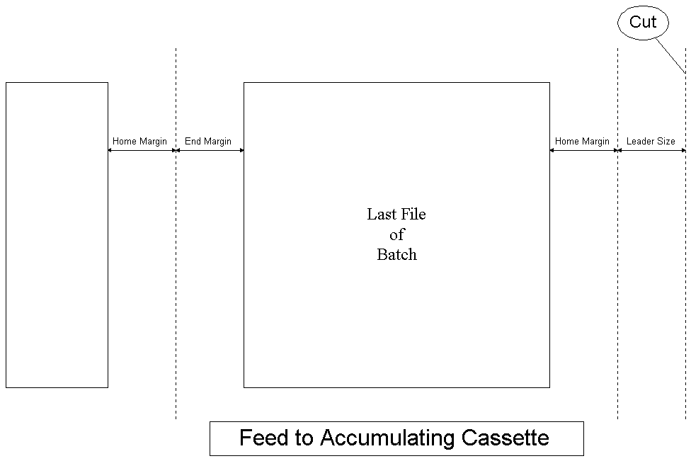
The following figure depicts the film unloading sequence to the
Accumulating Cassette. Before and after each file is exposed, Home Margin and End Margin
lengths are advanced through the Imagesetter drum. Film is collected continuously by the
Accumulating Cassette. After the last file in the batch is exposed, a Leader Size film
length is advanced and a Cut is performed.
Unloading to Accumulating Cassette
 Click to see the full size
Unloading to Inline Processor (ILP)
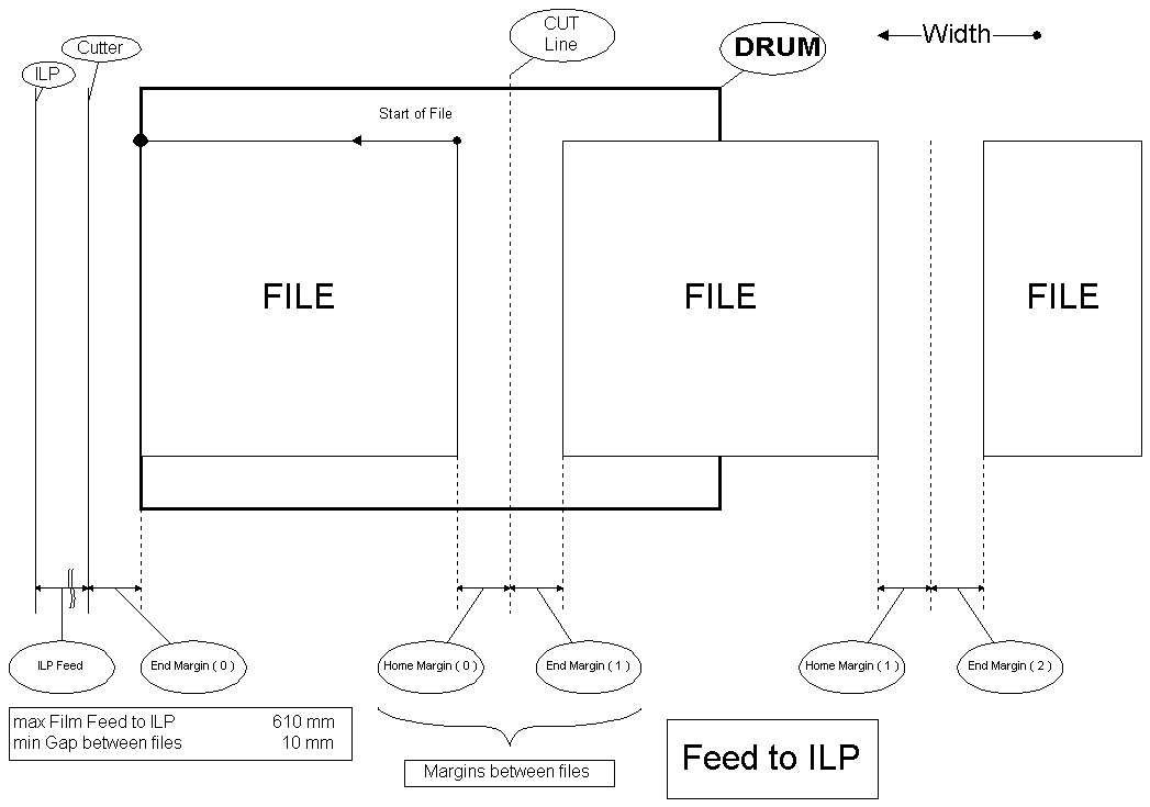
The following depicts the film unloading sequence to the Inline
Processor. Before each file is exposed a Width Home Margin length is advanced through the
Imagesetter drum. After each file, a Width End Margin length is advanced, and a Cut is
performed. Film is collected by the ILP.
Unloading to Inline Processor (ILP)
 Click to see the full size
Accumulator
Encoder Assembly
Encoder -
Assembly
Film loading and unloading is performed using three (3) encoders:
| |
Location
and Description |
| Loading Encoding |
At front left of Imagesetter, just behind the loading
rollers. Reports the length of film advanced from the Loading Cassette. Reports from this
encoder are also compared with reports from the Unloading Encoder in order to control
motor speeds. |
| Film Out Detector |
On the roller platen at rear left of Imagesetter. Reports
the length of film unloaded from thedrum. Reports from this encoder are also compared with
reports from the Loading and Accumulative Cassette Encoders in order to control motor
speeds and maintain the film buffer. |
| Accumulative Cassette Encoder |
On film entry plane at right side of Accumulating
Cassette. Reports the length of film entering the Cassette. Reports from this encoder are
also compared with reports from the Unloading Encoder in order to control motor speeds and
maintain the film buffer. |
Loading
Cassette
At front right of Imagesetter drum. Initially loads film from the
Loading Cassette into the Imagesetter drum, advances film between exposures, and provides
required film tension in drum. Used also to reverse film back into Loading Cassette
whenever the drum is emptied.
At rear right of Imagesetter drum. Advances film between exposures
and provides required film tension in drum.
Film Path
Selector
At rear right of Imagesetter, below drum. Drives the film cutter
back and forth on its chain.
Unloading
Cassette
Accum. Cassette Motor or Conveyor Motor
On right side of Unloading Drawer. Draws film into the Accumulating
Cassette. Between the Imagesetter and the Inline Processor (ILP). Draws film into Inline
Processor.
- Unload the film from the Imagesetter.
- Remove the Loading Cassette.
- Power off the imagesetter.
- Remove the unloading Motor:
- Disconnect the motor cable.
- Release the two screws that attached the motor bracket to the right
flange.
- Remove the motor. Make sure that the inner part of the coupling motor
will not fall down.
- Disconnect the part of the coupling from the roller edge.
- Release the two attachment springs. The unload outer roller should
not be attached to the drive roller.
- Open the rear cover.
- Remove the two center supports. The one of the drive roller and the
one of the outer roller.In order to remove the inner center support the on-line film
guides and the two funnel guides should be remove. Each film guide is supported by two
screws one from each side. Only release is needed in order to remove the guide.
- Remove the inner film guide.
- Release the roller bearing bushing ( two 4/40 screws ).
- Remove the bushing, spring washer and flat washer. ( on the left side
)
- Remove the roller from the left side of the imagesetter.
- Unload the film from the Imagesetter.
- Remove the Loading Cassette.
- Power off the imagesetter.
- Remove the Encoder finger. Use two keys, one inside the roller
special hole and one inside the finger hole. Make sure that the rubber ring on the encoder
wheel will not damage during this removal.
- Remove the black wheels from both sides.
- Open the rear cover.
- Remove the roller center support.
- Release the inner film guide. The two brackets on both sides of the
guide supports the outer film guide.
- Remove the outer film guide. (6 4/40 screws ).
- Release the roller bearing bushing (two 4/40 screws ).
- Remove the bushing, spring washer and flat washer (on the right
side).
- Remove the roller from the right side of the imagesetter.
Rocker
- Load/System
Disassembly
- Unload film from the imagesetter
- Remove the Loading Cassette
- Power off the Imagesetter
- Disconnect the Loading Encoder Cable
- Remove the solenoid assembly by releasing the two cross screws that
attached it to the frame.
- Release the two screws on each side that attached the fork to the
Rocker.
- Release the 1/4" screws from each side. Those screws are the
Rocker Shaft.
- Move the rocker to the release slot and remove the Rocker from the
Loading drawer.
- If the two springs are released remove the forks. It is possible to
remove the rocker and to leave the springs with the forks with the force.
Assembly
- Insert the rocker back to its place. Insert the two "shaft
screws".
Connecting the right fork
- Release the top cross screw of the spring holder. This will stop the
spring holder and will not allow it to rotate.
- Make sure that the rocker is in the lower position and set the right
spring to the right fork. Insert the two screws when the spring is inside the fork.
- Make sure that the fork will not touch the slot while the rocker is
moving between the upper position and the lower one.
Connecting the left fork
- Release the top cross screw of the spring holder. This will stop the
spring holder and will not allow it to rotate.
- Make sure that the rocker is in the upper position and set the left
spring to the left fork. Insert the two screws when the spring is inside the fork.
- Make sure that the fork will not touch the slot while the rocker is
moving between the upper position and the lower one.
- Make sure that the rocker is forced inside in the lower position and
it is open in the upper position.
- Connect the loading encoder cable.
To perform
assembly - Follow the Disassembly Procedure in reverse.
Disassembly Procedure
- Unload the film from the Imagesetter.
- Remove the Loading Cassette.
- Power off the imagesetter.
- Remove the Loading Motor:
- Disconnect the motor cable.
- Release the two screws that attached the motor bracket to the right
flange.
- Remove the motor. Make sure that the inner part of the coupling motor
will not fall down.
- Disconnect the part of the coupling from the roller edge.
- Remove the center support by releasing the two screws that attached
it to the V block.
- Remove the "film guide, loading inner" by releasing two
screws from each side. Regular screws on the right side and shoulder screws on the left
side.
- Remove the film in detector by releasing the one screw that holds the
detector on the left side.
- Release the two cross screws that hold the solenoid assembly.
- Remove the two 4/40 screws from the roller bushing (on the left
side).
- Remove the spring washer and the washer from the roller.
- Gently remove the roller to the left side.
Sometimes the Mouth assembly (between the unloading path & the
accumulative cassette) will not sit properly after disassembly and re-assembly.
It is important to pay special attention to the following
during mouth assembly:
During the installation of the mouth make sure that the top corner
of the mouth will not touch the lower door shaft holder. The mouth must fit and rest on
the flange on both sides.
In the future a change on new parts will be done and it will be
easier to install the mouth. |

