Detailed Maintenance Procedures For All ThermoFlex Mid and Narrow Devices
This (draft) document provides detailed descriptions of the planned maintenance (PM)
elements outlined in the Planned Maintenance (PM) Checklist, and follows the chronological
order of the checklist.
Check safety first. Determine that all components are safe to operate and work
on. Walk around the entire device to examine the exterior and surrounding area
for damange and any issues that may require further investigation or repair.
Site conditions: Record humidity and temperature readings on the
checklist and inform the opreator of any unfit conditions. See site preparation
guidelines if required.
Doors, panels, and interlocks: Open each door and panel. From the
ThermoFlex Controller software, check safety interlocks and verify that they
operate properly.
Exterior paint: Verify that there is no chipping.
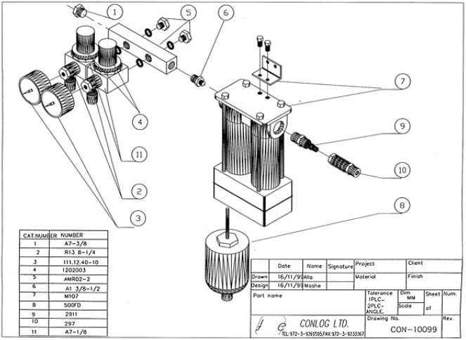
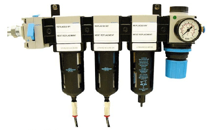
Compressed air: Verify that filters are replaced and that there are
no leaks.
Air supply pressure: Test and verify that pressure is 6 ATM (90 psi).
Exterior hoses: Visually inspect to verify that no exterior hose
is crushed or broken.
System operation and imaging
To check system operation and imaging, expose a test
file, as described in the ITP test files on the (Mid/Narrow)
Installation page. The test file serves as your reference. During the exposure
process, check the following:
Diagnostics: For Controller version 1.31.350.002 and later, run board
diagnostics. Note: Repeat diagnostic plate before returning platesetter to production.
ITP file quality: Assess the quality of the ITP file.
Anti-collision system: If the system is enabled, "cheat"
the anti-collision system and verify that the focus motor smoothly moves the
lens backwards.
Laser: Check maximum drum speed and compare the results with the
results of the last PM. Verify that laser power is within the specified range.
(See Drum speed calibration test (for flexo plates).)
Carriage: Listen for any irregular noises.
Drum vacuum: Verify that the plate is held firmly to the drum.
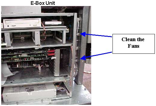
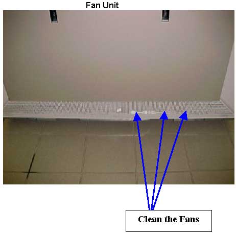
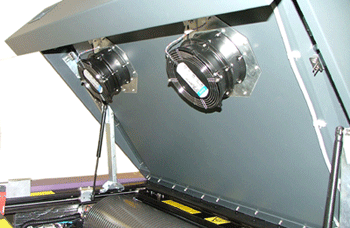
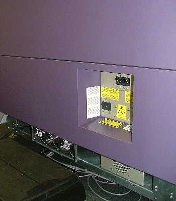
To maintain the fans in the locations listed following, use a vacuum cleaner
to clean the fans, and then check the fans to confirm sufficient air flow and
no unusual noise.
E-box
L-box
D-box
Service door (Mid II only)
L-box filter
Clean the L-box filter.
Detectors
Clean the balance and carriage Home Position (HP)/End Position (EP) detectors
with a cotton swab dampened with alcohol
Loading/unloading system
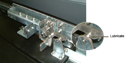
Loading table (Mid II only):
Spray WD®-40 lubricant onto a clean cloth and then lubricate
the loading table shafts. Important: Do not spray WD-40 directly onto the device.
Open the loading table, and then slide it back and forth to spread the
lubricant.
Unload roller (Mid II only): To access the unload roller, open the
loading table and then open the front panel. Then clean the metal unload roller
with a clean cloth and alcohol.
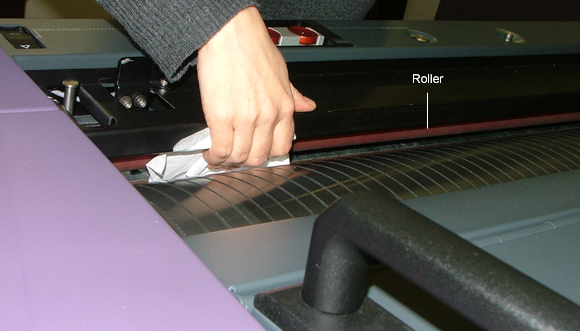
Roller (offset only): Clean the roller with a clean cloth dampened
with alcohol. Verify that the roller descends to the drum and revolves smoothly.
Then open and close the door and verify that the roller doesn't stick to the
drum.
Pins (offset only): Clean the pins with a clean cloth dampened with
alcohol.
Drum
Check the following drum-related components:
Internal vacuum hoses:
Verify that hoses are in good condition.
Drum surface:
Clean the drum surface with a clean cloth and a press
blanket (rubber rejuvenator).
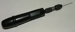
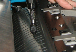
With the vacuum turned on, use the 0.8 mm drill from the accessory kit to clean
the top row of drum holes.
Remove any plates from the drum.
In ThermoFlex Controller, turn on the drum vacuum.
On the 0.8-mm drill, turn the chuck to open it, pull out the drill at least
1", and close the chuck.
Insert the drill at least 1" into a drum hole.
Swivel the drill to open and clean the drum vacuum hole.
Repeat steps 4-5 for each drum hole.
Note: Verify that the customer cleans the drum holes properly on a regular
basis.
Vacuum pump pressure
Before you begin, make sure that the machine has not
been working during the last 45 minutes, and that the drum
vacuum holes are open and clean.
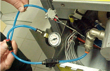
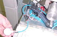
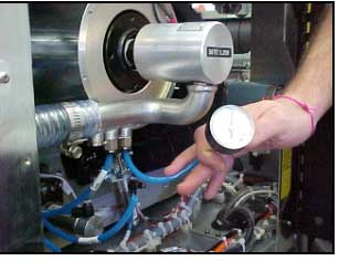
Connect the tube of the ACCU-AIRE vacuum gauge (PN 344C03012) to
the drum vacuum nipple below the swivel joint, as shown below. Note: This vacuum gauge, with resolution of 0.02 bar, has been tested
for accuracy.
Narrow: Old (left) and new (right) vacuum sensors
Mid: Vacuum sensor
Note: Use vacuum gauge by ACCU-AIRE with resolution of 0.02 bar (344C03012
- this gauge has been tested for accuracy).
Activate the vacuum pump, and verify that the vacuum guage tube is connected
correctly and does not leak.
After the pump is activated, wait at least two minutes. Verify that the
dial is vertical and the reading is stable, and then read the vacuum pressure.
Narrow:
The vacuum pressure (without plate) should be 0.13–0.17 bars
(3.8–5 in. mercury), or 0.82–0.88 bars (24.2–26 in.
mercury) with plate.
If the vacuum pressure is
lower than 0.13 bars (0.82 bars with
plate):
Check all tubes and connections between the pump and the drum—look
for leaks, bad connections, cracked tubes or leaking swivel.
Check the vacuum pump function:
Check the pump filter, as described in the vacuum
pump filter section, and clean or replace if required.
Measure the supply voltage on the distribution box at the
connection to the pump. The supply voltage should be 208 V (phase
to phase).
If the filter is clean and the supply voltage is 208 V, replace
the vacuum pump.
higher than 0.17 bars (0.88 bars with plate):
Clean the drum holes and check for other clogging in system.
Mid:
The vacuum pressure (without plate) should be 0.1–0.12 bars (3–3.5
in. mercury), or 0.82–0.88 bars (24.2–26 in. mercury) with
plate.
If the vacuum pressure is
lower than 0.1 bars (0.82 bars with plate):
Check all tubes and connections between the pump and the drum—look
for leaks, bad connections, cracked tubes or leaking swivel.
Pump performance:
Check the pump filter, and clean or replace if required.
Measure the supply voltage on the distribution box at the
connection to the pump. the supply voltage should be 208 V (phase
to phase).
If the filter is clean and the supply voltage is 208 V, replace
the vacuum pump.
higher than 0.12 bars (0.88 bars with plate):
Clean the drum holes, and check for other clogging in the system.
When the vacuum pressure is adjusted, stop the vacuum pump, disconnect the
vacuum gauge and reconnect the vacuum detector tube to the nipple.
Vacuum Pump
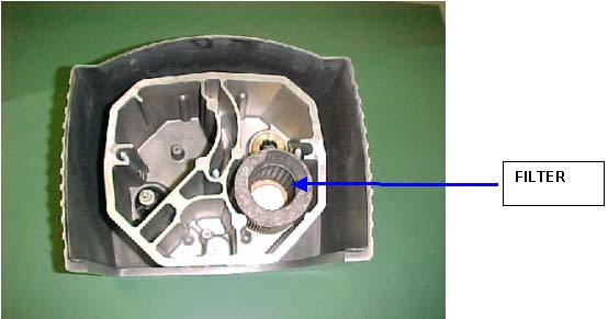
A clogged vacuum filter can reduce the vacuum, and may cause problems with
plate attachment to the drum. Maintenance intervals depend on the pump's use
and ambient conditions.
Narrow
Replace the filter every six months.
From ThermoFlex Controller, open the rear door.
Shut down the machine.
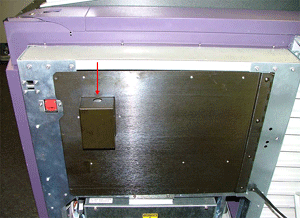
Remove the back panel.
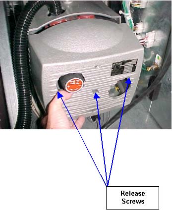
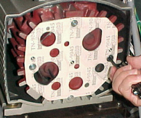
Remove the enclosure cover from the vacuum pump by releasing the three screws
as shown.
Replace the filter.
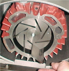
Remove the blades cover by removing the four hex screws.
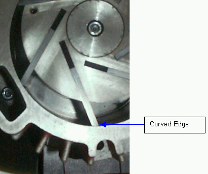
Pull out the seven vacuum pump blades one by one.
Using an external air pressure hose, clean the inside of the vacuum pump.
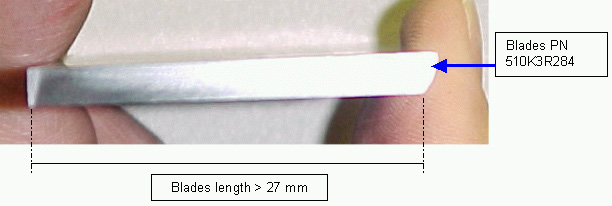
Using a calipher, measure the vacuum pump blades.
The width should be greater than 27 mm.
If the width of any of the vacuum pump blades is less than 27 mm, replace
all the blades in the set with a new set. Important: Insert the vacuum pump blades with the curved edge fitting
into the housing curve.
Secure the blades cover by tightening the four hex screws.
Reassemble the parts in reverse order.
Swivel
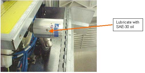
Lubricate the swivel with 4-5 drops of SAE 30 motor oil, and verify that the
customer lubricates the swivel every three months.
Narrow:
Mid:
If the inside side panel has a lubrication opening—put the oil dispenser
sprout into the hole to lubricate.
The nozzle should be clean and positioned properly.
In ThermoFlex Controller, click the Maintenance button.
The carriage moves to middle position.
The top door opens.
The vacuum debris removal is activated. Note: The vacuum must be on during the cleaning procedure.
Access the nozzle:
Mid II: Open the service door
Narrow: Lift and secure the loading tray. Note: If your device is an earlier model, remove the loading tray
by removing the two screws that secure it.
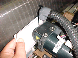
Cover the protective lens with a piece of folded rice paper, to protect
it.
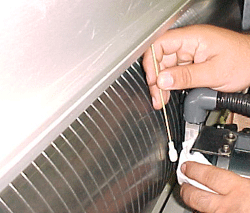
Use a cotton swab to clean the nozzle.
Optic lens
Once you expose without the UDRC or fuchs debris removal device, dirt accumulates
on the optic lens. A dirty optic lens can cause low throughput. To prevent low
throughput, clean the optic lens every six months. (Kodak plate users should
perform this procedure more frequently.)
In ThermoFlex Controller, click the Maintenance button and
open the top door or service door, as relevant.
If your device is a Narrow model, lift up the unloading tray. Note: On some of the older models, you must remove the four screws
from the unloading tray and remove the unloading tray.
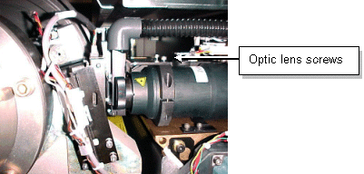
Remove the two hex screws on the optic lens assembly, as shown.
Turn the optic lens protective cover clockwise to open it.
Push the nozzle bracket as far as possible toward the drum. Note: If there is not enough room to lift out the lens protector, tilt
the carriage upward to enable lifting it out.
Use rice paper moistened with alcohol to clean the optic lens.
Install the lens protector, and secure it with the two hex screws that you
removed in step 4.
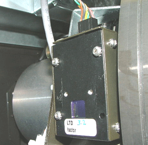
Dust, especially ablation dust due to plate exposure, can reduce detector
performance and reliability. Clean the light detector window with a cotton swab
dipped in alcohol. The frequency of detector maintenance depends upon machine
use and plate type.
V block and felt
Send the carriage to middle position.
Open the relevant doors and panels to allow access to the V-block.
If relevant, remove the unloading tray.
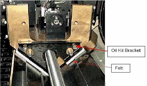
Remove the four screws that secure the oil brackets (two on each bracket)
and remove the oil brackets. Note: Keep the screws, they are used again later in this
procedure.
Dispose of the oil brackets.
Wipe off any oil and dirt from the V-block with a dry cloth.
Using 70% alcohol, clean the V-block to prevent ablation residue and dirt
from being absorbed into the oil.
In each new oil bracket, apply 3 cc silicon oil evenly along each felt,
and then allow the felt to absorb the oil for 2-5 minutes. Note: Platesetters have four felts.
Insert the oil brackets, and insert, but do not tighten, the screws that
you removed in step 4. Note: Use Loctite 242 on the screws.
Carefully push the brackets downward to allow the felt to be lightly pressed
against the V-block (or carriage beam).
Important: do not exert high force on the bracket.
Check the following according to your configuration:
UDRC: Verify that the customer records the working hours of the UDRC.
Fuchs: Record the serial number of the Fuchs vacuum and how many
hours it has been working.
Debris removal hose
Replace the debris removal hose annually:
To remove the debris removal hose from the platesetter:
In ThermoFlex Controller, send the carriage to mid position, and then open
the top/service door.
Manually open the front and side doors.
Turn off ThermoFlex Controller and then disconnect the main power.
Lift up the unloading tray. Note: On some of the older models, you must remove the four screws
from the unloading tray and remove the unloading tray.
Open the front and rear panels.
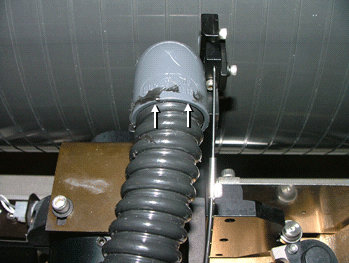
To release the debris removal hose, remove the silicon from the connection
point.
Cut all the tie wraps that secure the hose.
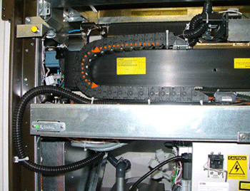
Open the section of the chain shown following.
Observe the path of the hose through the platesetter. After you remove the
hose and install the new one, you must route it through the platesetter along
the same path.
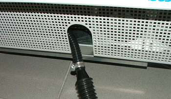
At the back panel, disconnect the hose from the adaptor.
Remove the hose from the platesetter.
To install the debris removal hose :
To prevent leakage, carefully spread RTV silicon glue along the edge of
the replacement hose, and connect the hose to the adaptor. Note: The silicon glue is not supplied with the PM kit.
Route the hose along the same path as the hose that you removed.
Thread the hose into the chain, and close the chain links.
Spread RTV silicon glue on the edge of the hose, and connect the hose to
the nozzle.
Secure the hose along its route with tie wraps.
Close the loading tray.
Close all panels and doors.
Expose an image solid and check that the solid is clean, without any artifacts
(lines) and that intensity is at least 0.06.
Air pressure regulator (for Narrow devices
only)
Replace filters every six months. See the PM part list for filter part numbers.