Home | Contact Us | Submit Troubleshooting Info | Search | Help
Output | Software Solutions | Proofing | Color, Screening and Calibration | Scanning | Digital Photography | Consumables | POS
Home | Contact Us | Submit Troubleshooting Info | Search | Help
Output | Software Solutions | Proofing | Color, Screening and Calibration | Scanning | Digital Photography | Consumables | POS
Dolev 4press - Assemblies
|
| CARD: | HOMC |
| COMP. LEVEL: | K |
| CAT: | 503D40815 |
LED
| Nr | Color | Definition | |
| 1. | XIL DONE | green | XILINX has done programming |
TEST POINT
| Name | Expected Signal | |
| 1. | -5.2V | -5.2V |
| 2. | DATA FRM A | DATA from Host A |
| 3. | DATA FRM B | DATA from Host B |
| 4. | DIAG DAT IN | Input for external data to be exposed |
| 5. | VCC | +5V |
| 6. | GND | DIGITAL GND (TP #1) |
| 7. | LAS VAL | LASER VALUE - Analog Signal - driving LDR's 60 mA current source. |
| 8. | +15V | +15V |
| 9. | -15V | -15V |
| 10. | +12V | +12V |
| 11. | KNEE VAL (EXTRA CURRENT) will be changed to "LAS EXT CUR" - Laser extra current - Analog signal - driving LDR's | 30 mA current source |
| 12. | LAS INT | LASER INTENSITY - Analog Signal - from the LDT |
| 13. | GND | DIGITAL GND (TP #2) |
| 14. | AGND | ANALOG GND |
| 15. | J4 (ANLG IN) | Analog input to be measured through Channel 8 of analog MUX |
In the Imagesetter E-box. Controls Dynamic Optics Carriage movement during exposure. Issues commands to the Stepper Driver and receives feedback from the Spinner.
LED
| Color | Definition | |
| 1. | Red | ALU error |
| 2. | Green | ENSTB |
| 3. | Red | PLL Unlock |
| 4. | Green | PROG DONE |
TEST POINT
| Name | Expected Signal | |
| 1. | Data Expsd | Expose clk |
| 2. | VCC | VCC |
| 3. | GND | GND |
| 4. | Sweep On | Sweep On |
| 5. | Clk | Encoder |
| 6. | Index | Index |
| 7. | PLL Feed | PLL Feedback |
| 8. | RREF PLL | Encoder |
| 9. | AGND | GND |
| 10. | POT1 VLT | Voltage on the potentiometer |
In the Imagesetter E-box. Controls the Spinner Motor.
JUMPERS / DIP SWITCH
| Nr | State | |
| 1. | 1-6 | ON THE ELMO BOARD - ALL 6 SWITCHES OFF |
LED
| Nr | Color | Definition | |
| 1. | LED ON THE PCB | RED | LOW - ON SPEED LOCK, HIGH - O.W |
| 2. | LED ON ELMO | YELLOW | POWER TO THE ELMO CARD IS OK |
| 3. | LED ON ELMO | RED 1 | LOW - OK, HIGH - BAD |
| 4. | LED ON ELMO | RED 2 | LOW - OK, HIGH - BAD |
| 5. | LED ON ELMO | RED 3 | LOW - MOTOR ON HIGH MOTOR ON |
In the Imagesetter E-box. Controls the ND Filter Motor during laser light calibration.
| CARD: | DC_MOTOR_DRIVER |
| COMP.LEVEL: | L |
| CAT: | 503C36825S |
LED
| Nr | Color | Definition | |
| 1. | D1 | green | PWR12V is OK |
| 2. | D59 | red | high temp |
| 3. | D4 | red | ND filter protection |
| 4. | DD7 | red | spare motor protection |
| 5. | D5 | red | cutter motor protection |
| 6. | D6 | red | cassette motor protection |
| 7. | D7 | red | unload motor protection |
| 8. | D8 | red | load motor protection |
| 9. | DD6 | red | spare solenoid protection |
| 10. | D2 | red | unload solenoid protection |
| 11. | D3 | red | load solenoid protection |
FUSE
| Name | Value | |
| 1. | F16 | 5A/125V |
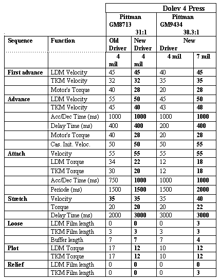
| Date: January 1, 1996 (GM9434) Ilan Blaus - m_param4.doc |
** The parameter values for the new motors are still under test. Some
changes are possible !! ** The last update for 7mil column was done on 5/12/95.The new params are tested on plate 8mil and film 7mil. |
| LDM - LOAD MOTOR | Old Driver | DC MOTOR DRIVER | Cat # 503C36825S | [Comp level = L] |
| TKM - TAKE MOTOR | New Driver | DC MOTOR DRIVER II | Cat # 503C40798S | [Comp level = K] |
CPU Board
Hard Drive
| CARD: | POWER CONTROL BOARD |
| COMP.LEVEL: | C |
| CAT: | 503C38040 |
FUSE
| Name | Value | |
| 1. | F1 | 6.3A |
| 2. | F2 | 6.3A |
| 3. | F3 | 6.3A |
In the Imagesetter D-Box. Receives rasterized data from the Host, processing this information for issuance to the HOMC.
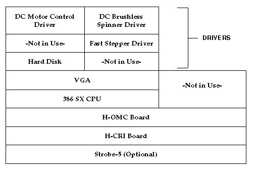
 Click to see the full size
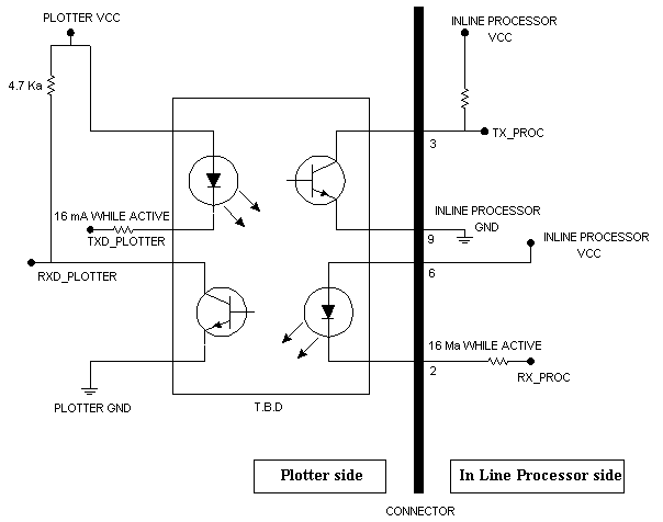
 Click
to see the full size
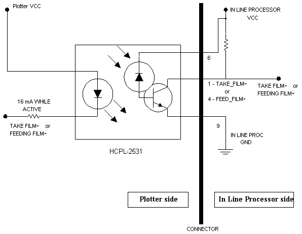
 Click
to see the full size