Home | Contact Us | Submit Troubleshooting Info | Search | Help
Output | Software Solutions | Proofing | Color, Screening and Calibration | Scanning | Digital Photography | Consumables | POS
Home | Contact Us | Submit Troubleshooting Info | Search | Help
Output | Software Solutions | Proofing | Color, Screening and Calibration | Scanning | Digital Photography | Consumables | POS
Serial numbers start with NM (TMCE) or NG (GMCE)
This page is no longer being kept up-to-date. If you are looking for information about FRUs for GMCE and TMCE NEWS devices, use the FRU locator instead.
Top level assemblies
Disassembly kits
Trendsetter NEWS—02-4289B
Drawing not available | BOM
Final Assembly, NEWS, TSM—11-0976
Drawing not available |BOMFinal Assembly, NEWS 200, TSM—11-1019
Drawing not available |BOMMainframe, NEWS, TSM—11-0977
Drawing |BOMMainframe, NEWS 200, TSM—11-1020
Drawing not available |BOMCommon parts kit—11-1025
Drawing not available |BOMCommon parts kit, NEWS 200—11-1021
Drawing not available |BOMPreloader interface - for NEWS 150, 200 only
Preloader interface, MPE—11-1139A
Drawing not available |BOMNELA preloader interface—11-1063A BOM
Preloader interface board—10-5072APreloader interface, MCE—11-1140A
Drawing not available |BOMNELA preloader interface—11-1063A BOM
Preloader interface board—10-5072AAL, Non-Rotator NEWS kit—11-0933B
Drawing not available |BOMAL, Rotator NEWS kit—11-0816B
Drawing not available |BOMSee Autoloader Assemblies for detail
Blanking panel assembly—50-1947A
Drawing not available |BOMFly-off sensor kit—10-4996
Drawing not available | BOM
Upgrade Kit 1.7 to 2.0—50-2149A
Drawing not available | BOM
TEH1.7, Common Part kit—11-1023
Drawing not available |BOM
TEH2, Common Parts kit—11-1022
Drawing not available |BOM
TEH2, Common Parts kit, NEWS 200—11-1024
Drawing not available |BOM
Exposure head 1200 dpi, TH 2.25—32-4197
Drawing not available | BOM
Load Ramp—50-2426B
Drawing
| BOM
Lower ramp cylinder, home 50-1653A Drawing|BOM
Upper ramp cylinder, home or away (FRU)—512-00263A - kit contains 2 cylinders plus all fittings Drawing - see FCO CA06235
Plate sensor—36-3210
Plate sensor to MCE cable—10-4683
Drawing
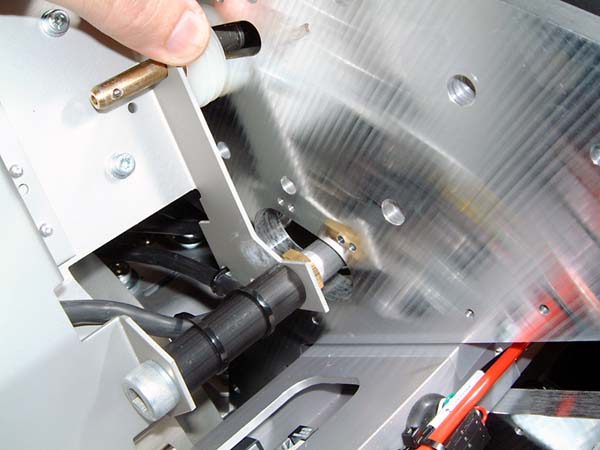
Nylon spacers 52-3323 - 5 pieces home side, 6 pieces away side photo
Spacers should not be too tight—allow 1 mm of movement after spacers installed.
Load Table (non-rotator)—50-2425C
Drawing
| BOM
Plate ledge assembly—50-2459
Drawing | BOMPlate ledge flathead screws—52-7177Plate sensor—36-3210
Picker vacuum generator—340-00001
Order kit 518-00114A to replace failed vacuum generator (340-00001 or 55-0632) or muffler (55-0569).Door lock solenoid—10-3739A
Door lock safety switch—10-3805Operator door, Gas strut cylinder—330-00080 see CA04191
Warning light bulbs—36-3156 (part of assembly 10-3742A)
Corner lights—10-3741A Drawing (NM227 and lower)
Load Table (rotator)—50-1525E
Drawing
| BOM
Bay door
Door lock solenoid—10-3739A
Door lock relay—10-3800B
Gas strut cylinder—330-00080 see CA04191
Plastic ball coupling for gas strut cylinder—368-00086
Gas strut ball stud—55-0199
Right hinge—59-3291
Left hinge—59-3292
Load table support bracket - 57-5450APlate ledge assembly—50-2154
Drawing | BOMPlate separator arms—see page 2 of 50-1525D Drawing and specific parts on 50-1525 BOM
Separator arm kit—50-2689A BOM
Separator cylinder—55-0574
Separator bracket—05-0076
Microswitch for plate separator arms— see page 2 of 50-1525D Drawing and see specific parts on 50-1525 BOM
Separator microswitch—15-3135
Separator microswitch bracket—57-4831BPlate sensor—36-3210
Picker vacuum generator—340-00001
Order kit 518-00114A to replace failed vacuum generator (340-00001 or 55-0632) or muffler (55-0569).
Warning light bulbs—36-3156 (part of assy 10-3742A) (NM227 and lower)
Corner lights—10-3741A Drawing
Manifold—50-2466B
Drawing
| BOM
Valve, Single Solenoid—55-0771
Valve, Double Solenoid—55-0954
Operator Door—50-1992A Drawing | BOM
Lower Operator Door (purple)—50-1931C Drawing
Lower Operator Door (white-gray)—50-1931B
Panel Kit TS8 AL—50-1973A BOM
Operator Interface—50-1522B
Drawing
| BOM
Board—10-1420 Drawing
Start button—10-4340
Picker, Version III—50-2423
Drawing
| BOM
Picker Head Assembly—50-2424
Drawing | BOMPicker head in/out cylinder kit—518-01238A - includes 2 cylinders and 2 elbows
cylinders on both sides should be replaced
Picker wrist cylinder—330-00002 see FCO CA00567 Wrist Cylinder Upgrade
Suction cups W\O valve, silicone, red—55-0706
Vacuum Generator—340-00001
Order kit 518-00114A to replace failed vacuum generator (340-00001 or 55-0632) or muffler (55-0569).
Wrist sensor cable assembly—10-4579APicker move up/down cylinders
Right—50-1761A Drawing | BOM
Left—50-1762A Drawing | BOM
55-0804 (cylinder only)
Picker move wrist cable assembly—10-5110Picker rails
Right—50-1763B Drawing | BOM
Left—50-1764C Drawing | BOMOptical sensors on rails—order kit 518-01911A (FCO CA10840) to replace 10-3676A
Picker rail bottom bracket—57-6000A (item 30 on 50-1763B and 50-1764C drawings)Picker guide cable (Stainless steel)—50-1765A
Lower pulley for guide cable (Picker 3) 57-6015A Drawing
Pulley 1, Move Cylinder (Larger upper pulley for Picker 3) 57-6016A Drawing
Pulley 2, Move Cylinder (Small upper pulley for Picker 3) 57-6017A Drawing
Bushing,1/4"*5/16"*1/2",Bronze 54-4024Miscellaneous
Speed ctrl 0.1mm orfice—55-0807
Speed ctrl 0.2mm orfice—55-0806Sensor reed switch—15-3063
Magnet for reed switch—59-3141
Non-rotator
Short pan (non-rotator)—50-2427B
Drawing | BOMTraveler—50-2428
Drawing | BOMMotor/drive pulley assembly—50-1496B BOM
Motor assembly kit – 512-00256A Drawing | BOM (this kit to be ordered by field service engineer)
Motor only—15-3234 (FYI only)
Drive pulley—50-1756B (see FCO CA02183)
Rubber spider in coupling between pulley and motor—50-0231
Plate eject sensor—36-3210
Suction Cup—55-0541
Traveler home/away optical sensor—10-3683Short bridge—50-1617A
Drawing | BOMUnload table replacement pans
Center panel—57-4870A
Left panel—57-7322A
Right panel—57-7321A
Rotator
Long pan (rotator)—50-1492A
Drawing | BOM
In addition to the parts listed under non-rotator:Rotating traveler—50-1458A - includes cable track
Drawing | BOMFlex track—10-3678D See E876
Suction cup up/down cylinder—55-0257
Suction cups—55-0541
Rotate cylinder—55-0619
Traveler rotate magnet—59-3141
Traveler rotate sensor—15-3063Long Bridge—50-1456B
Drawing | BOMUnload table pan replacement kit—50-2452A—includes top panels and panels to right and left but does not include bridge panels
Unload Table 50-1449B
Drawing | BOM
Lexan side panels (non-rotator) 500-01928A Assembly Drawing
OR
Lexan side panels (rotator) 500-01927A Assembly DrawingRear cover panel 50-1535A Assembly Drawing
Unload cylinder 50-1493A Assembly Drawing |BOM
- Cylinder only 55-0604
- Orifice for non-rotator table 55-1188 Drawing item 20
- Orifice for rotator table 55-1187 Drawing item 20
Clevis and Pin Kit 50-2341A FCO E100
Kit includes:
- 52-4488 Cotter pin, auto locking, 1/2" shaft (2)
- 52-4064 M12 washer (4)
- 52-4897 Clevis pin, 7/16"*2.5" (2)
- 55-0605 Rod end, clevis, 5/8" - 18, 0.43 Pin (2)
Plate pusher—50-1690
Drawing |BOMSafety guard—57-5245
Processor transition bridge, 850 mm—500-02337B
Drawing | BOMProcessor transition bridge, 1350 mm—500-02339B
Drawing | BOM
Air Supply Filter/Regulator combination, TSM—55-1220A
Drawing | BOM
Filter replacement kit—332-00003 contains:5 micron filter
0.01 filter
O-rings
Carriage motor and Pulley—11-1133C
Assembly Drawing | BOM
Order entire assembly. Do not order pulley or motor separately.
Carriage motor cooling assembly—11-0885A
Drawing |
BOM
(fan #10-4521A)
Carriage motor mount—50-1623
Drawing | BOM
Carriage Adapter Plate (TEH 1.7 to 2.0)—50-2476
Drawing
Carriage drive board—503C01525B (see FCO CA00752)
Engine, NEWS,TSM—50-2393
Assembly Drawing | BOM
Engine, NEWS 200,TSM—50-2462 BOM
Ballscrew hanger—50-1620
Drawing| BOM
You must replace entire assembly #50-1620 since the bearing cannot easily be removed from the hanger.Clamp cylinders (all*), drive (away) end—50-2683B
Drawing| BOM
*There are 3 individual cylinders included in the top level assembly noted above, if you require only single cylinders here are the part numbers:
LEC (away) - 50-1655A
TEC (away) - 50-1656A
ROLLER (away) - 50-1657AClamp cylinders (all*), home end—50-2684B
Drawing | BOM
*There are 3 individual cylinders included in the top level assembly noted above, if you require only single cylinders here are the part numbers:
LEC (home) - 50-1652A
TEC (home) - 50-1651A
ROLLER (home) - 50-1650ADrum motor assembly—50-2160
Drawing| BOMDrum motor—15-3453
Drum motor timing belt—54-3894Drum motor cooling assembly
11-0886A—for serial number NM537 and lower
Drawing |BOM
500-03394A—for serial number NM538 and higher (100 label number 27)
fan—10-4521AEdge Detection Strip—57-3826A Drawing
Encoder assembly—507-00165A (replaces 32-4130A - Jul 2004)
Drawing | BOMFrame/track assembly, TSM-NEWS—50-2463B
Drawing | BOMLeading edge actuator—50-1087B
Drawing| BOMLE Clamp, low profile with dowel pin installed—500-03262A (NM440 and above - replaces 50-2114B)
LEC pivot blocks kit—512-00260A (see FCO CA06616)Manifold, solenoid valve—50-1649B
Drawing | BOMRoller TSM—50-2685
Drawing | BOMTEC North magnetic clamp—50-1091 - for devices with reed switch backbone
Drawing| BOMTEC South magnetic clamp—50-1131 - for devices with reed switch backbone
Drawing| BOMTEC magnetic clamp—500-04229A - for devices with optical sensor backbone (FCO CA03738)
DrawingTrailing edge actuator with magnets—50-2744
Drawing | BOMTEC Backbone—50-2730
Drawing | BOMMicroswitch—15-3478
Microswitch bracket—57-8893A
Fan box—11-0604 BOM
NEWS 200 fan box—11-0972 BOM
Fan box panel grill—57-7290B Assembly Drawing
Cooling system pump/motor
Water pump—510P1P973A
NEWS 200 water pump—378-00015
Motor—500-03677A
NEWS 200 motor—500-03282A
If motor fails, replace both motor and pump. If pump fails, replace pump only.Water Reservoir Assembly—50-2173A
Drawing | BOM | Cooling System SchematicCaplug, .281” ID, 1” long, natural silicone—59-3760
Input cap assembly—50-2164A Drawing | BOM
Mounting bracket—57-8970A
Reservoir—57-8166B
Strainer basket—57-8167A
Coolant—82-1032ACoolant hoses and fittings
Hose/fittings, reservoir to pump—50-2451A photo
Hose/fittings, pump to heat exchanger—50-2339A photo
Hose/fittings, heat exchanger to thermal imaging head—50-2450B photo
Hose/fittings, thermal imaging head to reservoir—50-1925E photo
Coolant connector O-ring—59-3415 photoNEWS 200 only
Hose, heat exchanger to heat exchanger—50-2348A photo
Hose, heat exchanger to thermal imaging heads—50-2340B
Hose, thermal imaging heads to heat exchanger—50-2338B
Common Panels—50-2495
Drawing | BOM
Gas strut (cylinder) that supports front door
—55-0564 (for serial number NM313 and lower)
—362-00063 (for serial number NM314 to NM621, see FCO CA10120 to replace 55-0564)
Panels—50-2405
Drawing not available | BOM
Top Panel Kit—50-1685
Drawing | BOM
Power box assembly—11-0910
Assembly Drawing | BOM
Safety Assembly—11-0983
Assembly Drawing | BOMPower box panel grill—57-7290B Assembly Drawing (used until late 2003 for power box) or 252-00507A Assembly Drawing (used from late 2003)
Electronics tray—11-0925
Drawing | BOMGMCE board—503-08443E
TMCE board—10-4766
Power distribution board—10-4112
Carriage drive board—503C01525B (see FCO CA00752 to replace 10-4935)Power supply tray—11-0924
Drawing | BOMPower supplies
PS1: Order kit 500-02643A to replace 166-00056 or 13-5094
PS2: Order kit 500-02645A to replace 166-00058 or 13-5094
PS3 (TH1.7 and TH2): Order kit 500-02646A to replace 166-00057 or 13-4832
PS3 (NEWS 200): Order kit 500-02647A to replace 166-00059 or 13-4791
PS4 (TH1.7): Order kit 500-02648A to replace 166-00057 or 13-4832
PS4 (TH2): Order kit 500-02649A to replace 166-00059 or 13-4791
PS4 (NEWS 200): Order 13-5165
See Power Supplies for more details.Drum amp tray—11-0926
Drawing | BOMMain drive amp/servoamp/drum amp—15-3466 (serial number NM470 and lower)
Main drive amp/servoamp/drum amp—601-00032 (serial number NM471 and higher—100 label #26)
Drum brake board—10-4883
See MCE Power Box page for more detail.
NEWS disassembly kit—50-2292 BOM
Trendsetter common add-on parts disassembly kit—50-2323 BOM
Common boxed parts disassembly kit—50-1923 BOM
NEWS SA disassembly kit—518-00653 BOM