Home | Contact Us | Submit Troubleshooting Info | Search | Help
Output | Software Solutions | Proofing | Color, Screening and Calibration | Scanning | Digital Photography | Consumables | POS
Home | Contact Us | Submit Troubleshooting Info | Search | Help
Output | Software Solutions | Proofing | Color, Screening and Calibration | Scanning | Digital Photography | Consumables | POS
ASAP | Next Visit | Next Failure | Next PM | FYI
| FCO | Date Posted | Description | Service Actions | 100 Label # | Priority |
|---|---|---|---|---|---|
| D788 | Sep 2000 | Part # 18-3243, a rubber boot insulator, is a
safety hazard and must be replaced with part # 18-3355.
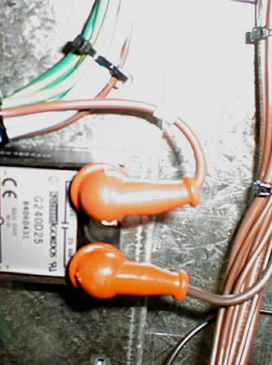 |
See FCO
D788 and the procedure
Order kit #05-0166. |
5(TS8)
27(TS3) |
ASAP |
| FCO | Date Posted | Description | Service Actions | 100 Label # | Priority |
|---|---|---|---|---|---|
| CA09835 | Mar 2008 | Add a safety cover over the drum drive V-belt and pulleys to prevent pinch and entrapment accidents. Applies to TMCE Trendsetter output devices with the drum drive V-belt that were shipped prior to the introduction of the safety cover (serial numbers TM1017 to TM1081 for Trendsetter 400/800 base, AL, and CL, and NM538 to NM588 for Trendsetter NEWS). | Install upgrade kit #512-00365A. Upgrade procedure Related procedure: Aligning and tensioning the drum drive V-belt |
23 (TMCE Trendsetter 400/800 base, AL, and CL) 28 (TMCE Trendsetter NEWS) |
Next visit |
| CA12332 | May 2007 | Replace the UDRC bulkhead on GMCE Trendsetters with a conductive-coated bulkhead plate to prevent EMC-radiated noise leakage. Applies to serial numbers TG0362 and lower, and NG0261 and lower. | Install upgrade kit #512-00442A. UDRC Bulkhead Plate Upgrade Procedure |
3 (GMCE) | Next visit |
| CA10122 | Aug 2006 | Replace mechanical film guide’s LEC (away side) guide mount. Applies to MCE Trendsetter output devices with the drum drive V-belt (serial numbers TM1018 to TM10163). | Install upgrade kit #512-00372A. FCO CA10122: Mechanical Film Guide Mount Upgrade Procedure |
25 (MCE) | Next visit |
| CA08946 | Dec 2005 | Update 1 for Trendsetter 400/800 base, AL, CL, and Spectrum Controlled Release MCE 4.1. This update fixes a flyoff problem for Spectrum devices and reduces the unload table hold current of the traveller motor to prevent the motor from overheating on Autoloader and ContinuousLoad devices. You must have CR 4.1 installed before installing this update. | See Trendsetter 400/800 Controlled Release MCE 4.1, Update 1 | Next visit | |
| CA05160 | Sep 2004 | FCO CA00752 introduced a new carriage driver
board (503C01525B), which has a switching power supply that generates a
high level of electrical noise. This noise is fed into the MCE board via
carriage driver board power cable 220-00061A, which can cause SCSI CRC
check errors, digital I/O errors, and low-level firmware errors. Applies to TM520 and lower |
Replace carriage driver board power supply
cable 220-00061A with cable 220-00163B. The new cable connects directly to
the power supply (PS2), so does not feed noise into the MCE board.
See procedure: Replacing the Trendsetter Carriage Driver Board Power Supply Cable (FCO CA05160) |
13 (MCE) | Next visit |
| CA04904 | Jul 2004 | Wrong pin used for load ramp sensor extension cable (10-5155A) that could cause cable failure. This cable was used in devices with serial numbers TM042 to TM467. | Replace with cable 10-5155B. This cable replacement applies to devices with serial numbers TM042 to TM467. | 12 (MCE) | Next visit |
| CA03275 | Jan 2004 | Trendsetter 400/800 Controlled Release MCE 3.2 | See the Control-Settings page for more information. | N/A | Next visit |
| CA02432 | Nov 2003 | Trendsetter 400/800 Controlled Release MCE 3.0 | See the Control-Settings page for more information. | N/A | Next visit |
| CA01954 | Aug 2003 | Trendsetter 400/800 Controlled Release MCE 2.0 | See the Control-Settings page for more information. | N/A | Next visit |
| CA01615 | Jul 2003 | Trendsetter 400/800 Controlled release MCE 1.2 | See the Control-Settings page for more information. | N/A | Next visit |
| CA00778 | May 2003 | Trendsetter 400/800 Controlled release MPE 1.2 and MCE 1.1 | See the Control-Settings page for more information. | N/A | Next visit |
| CA00386
see Note: |
Feb 2003 | Kit available for UDRC-LC connectivity. | Kit# 512-00043
Note: MCE only |
2 (MCE) | Next visit |
| CA00398
see Note: |
Jan 2003 | TEC lock/unlock sensors are getting damaged during operation. New guide will protect sensors from contact with lock/unlock tabs. | Install new guide (252-00551A). See detail A in Assembly Drawing.
Kit 512-00022 Note: MCE only |
3 (MCE) | Next visit |
| E854 | Jun 2002 | Trendsetter 400/800 Controlled Release MPE 1.0 | See Controlled Release 1.0 for details and ordering information. | 18(TS8)
30(TS3) |
Next visit |
| E312 | Sep 2001 | Load ramp sensor #36-3141 has wrong focal length. Replace with #36-3210. | See FCO E312 for information. | N/A | Next visit |
| E040 | Feb 2001 | Each service person will carry their own safety
key and will remove keys from installed machines.
|
See FCO E040 for information. | N/A | Next visit |
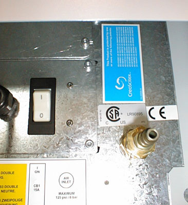
| D973 | Feb 2001 | Apply patent labels (#74-3305A) to all machines
and heads.
|
See Photos for label locations. | N/A | Next visit |
| D955 | Dec 2000 | V-speed upgrade to improve reliability at high
throughput
Applies to TE067, TE076, TE079 and TE089 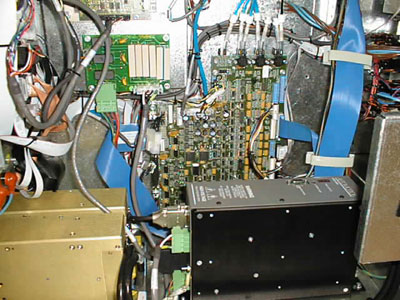 |
See Speed Enhancement Upgrade for photos. | 8(TS8)
|
Next visit |
| C961 | Jul 1999 | Vacuum plugs on the drums cause reflections.
Optical encoder is unreliable. |
On next service visit, install decals 74-3236A
on all drums with vacuum seal discs behind the encoder disc. See
instuctions in FCO
C961
Replace encoder assemblies 32-3011B or 32-4047A with 32-4047B if encoder still failing after cleaning and aligning. |
22(TS3) | Next visit |
| X1
Note: X1 denotes a parts swap rather than a part number change |
Jun 1999 | This FCO calls for the replacement of the — TEC backbone, 50-1088A — on 81 output devices including Platesetters, Trendsetter, and Proofsetters. The TEC backbones on these output devices are all from the same batch lot assembled with the wrong type of Loctite that will eventually cause them to loosen and fail over time. | Treat this FCO as a recall: schedule a visit, replace the assembly, and return the old assembly to Creo Annacis for refurbishing. | Next visit | |
| C953 | Jun 1999 | The existing TS3 machine with a 1.7 head does
not satisfy European emission standards. This FCO releases a kit to
upgrade a machine to compliance.
Kit #50177A Applies to all TS3244 machines with 1.7 heads. Implemented on production machines ~S313. Photo |
See EMI Upgrade Procedure.
Implemented on production machines ~S313. |
19(TS3) | Next visit |
| C904 | Jun 1999 | Customers can't always find the machine serial
number when placing a call to the response center.
Kit 05-0105 |
Attach a label with a Service Reference Number to each machine in the field. See instructions in FCO C904. | Next visit | |
| C853 | May 1999 | All shipped TS3-based units that have the 1.7
water-cooled head option have a 2" air cooling hole. This hole
is a potential laser safety problem and must be fitted with a blocking
plate.
Kit 05-0108 |
Install blocking plate. See the Water Cooling Kit Laser Blocking Plate Install Assembly Drawing . | 20(TS3) | Next visit |
| C694 | Mar 1999 | Adds SPI filters to the Trendsetter Interface
board 10-1419C.
The SPI filter daughter boards (10-3647A and 10-3669A) reduce the
effect of high frequency noise.
|
Required on S65 and earlier for CE compliance to ESD noise. | Next visit | |
| C624 | Dec 1998 | For certain Trendsetter sites running film, the
system blower is causing the film to buckle during loading. The temporary
solution of disconnecting the fan is not desirable. FCO C624
adds a fan baffle to the system blower so flow is directed away from the
edge of the drum and the film. The affected machines are S94-S161.
Kit # 05-0078 |
Any Trendsetter running film with a squirrel cage fan and no TEE board requires this upgrade. The squirrel cage fan can be identified by the square cutout in the back of the fanbox. Check serial numbers S94-S161 for fan baffle on the system blower | Next visit at customer sites running film. | |
| C572 | May 1999 | Install Spectrum Machine Back Panel
Field Upgrade Kit: 05-0067 (JV-Grey), 05-0068 (Creo-Grey) |
Trendsetters in the field without the panel (mostly Spectrums) should have this panel added at the next call. | 15(TS3) | Next visit |
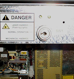
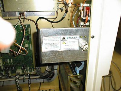
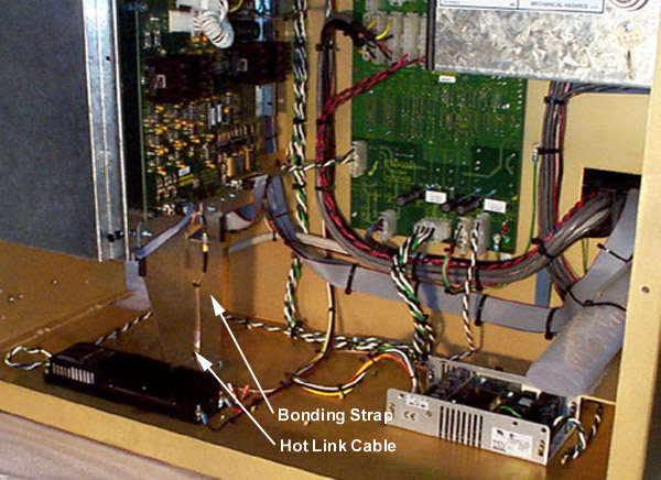
| B991 revised | May 1998 | Implement a Service Interlock Override (SIO)
keyswitch assembly for the Trendsetter power box, to meet the following
requirements:
|
This revision to FCO # B991 must be implemented
for all Trendsetters in the field. Refer to the Mainframe-Electronics Schematic
and the Powerbox Schematic
during the procedure.
To ease in any future upgrade to the Spectrum or Autoloader options, the SIO installation procedure requires routing two additional cable assemblies via the power box flex track. |
1(TS3) | Next visit |
| B768 | Jun 1997 | Upgrade of the the PS1 power supply (10-3213) in Trendsetter 3244/3230, Autoloader and Spectrum machines from a Vicor FlatPac style design to a Power One open frame type. See upgrade procedure. | This upgrade is not mandatory for all Trendsetters and should only be carried out if a replacement Vicor FlatPac is not available for exchange. | Next visit | |
| A829 | Aug 1996 | Plate alignment sticker placement | Next visit | ||
| A738 | Jul 1996 | Replace incorrect voltage label in fan box | Next visit |
| FCO | Date Posted | Description | Service Actions | 100 Label # | Priority |
|---|---|---|---|---|---|
| CA10120 | Jul 2006 | New struts for front panel. For serial numbers TM676 to TM1130. These struts cannot be used on Spectrum devices. | If the old front panel strut (55-0564) fails, order kit number 512-00368A. This kit is an upgrade from a single strut to a dual-strut design. Dual Strut Upgrade Procedure | 24 | Next failure |
| CA09771 | 18 Apr 2006 | Replacing chiller with heat exchanger for Trendsetter 3230/3244 (TS3 and TS3/8). | Replace defective chillers with heat exchangers. For details see the Heat Exchanger page. | N/A | Next failure |
| CA03931 - TS3 and TS3/8 | Sep 2005 | Change TEC reed or microswitches to optical sensors on
TS3 and TS3/8 MPE devices to improve reliability. The procedure involves replacing
the old TEC backbone with a new TEC backbone. For serial numbers S001-S387
and S983631001-S993631323.
Note: This FCO should only be applied if there have been repeated failures of the TEC backbone, clamp microswitches and/or reed switches. Do not apply this FCO for an individual switch failure. |
Order kit number 512-00123B.
TEC Optical Sensor Upgrade Procedure (TS3 and TS3/8) Return old TEC backbones for reworking. |
N/A | Next failure |
| CA03931 - TS4/TS8 Heidelberg-built devices | Sep 2005 | Change TEC reed or microswitches to optical sensors on
TS4/TS8 Heidelberg-built devices to improve reliability. The procedure involves replacing
the old TEC backbone with a new TEC backbone. For serial numbers Sxx386xxxx (TS400/800), Sxx371xxxx (TS4), and Sxx385xxxx (TS4).
Note: This FCO should only be applied if there have been repeated failures of the TEC backbone, clamp microswitches and/or reed switches. Do not apply this FCO for an individual switch failure. |
Order kit number 512-00103C.
TEC backbone optical upgrade for TS4/8 Heidelberg-built devices Return old TEC backbones for reworking. |
22 | Next failure |
| CA07165 | Jul 2005 | New, more reliable cooling circulation pump and motor | If the old pump fails, replace the pump only. If the old motor fails, replace both motor and pump. Water pump: 510P1P973A Motor: 500-02914A |
N/A | Next failure |
| CA06199 | May 2005 | Mean Well power supplies replacing Astec power supplies. Factory installation of these power supplies started at serial number TM736 and NM344. PS4 for NEWS 200 has not changed. |
Order kit number: • 500-02643A for PS1—Procedure • 500-02645A for PS2—Procedure • 500-02646A for PS3 for TH1.7 and TH2—Procedure • 500-02647A for PS3 for NEWS 200—Procedure • 500-02648A for PS4 for TH1.7—Procedure • 500-02649A for PS4 for TH2—Procedure |
17 (MCE) 21 (NEWS MCE) |
Next failure |
| CA06616 | May 2005 | More reliable pivot blocks for all Trendsetters Factory installation of these pivot blocks started at serial number TM751 and NM354. |
Order kit 512-00260A that contains 2 short and 5 long pivot blocks, 7 screws, and Replacing pivot blocks (CA06616) procedure. | 20 (MCE) 23 (NEWS MCE) no 100 label # for MPE |
Next failure |
| CA04411 | Jun 2004 | Update 1 for Trendsetter 400/800 Controlled Release MCE 3.2. This update should only be applied to solve specific UDRC problems on devices that have Trendsetter 400/800 Controlled Release MCE 3.2 installed. | See Trendsetter 400/800 Controlled Release MCE 3.2, Update 1 | Next failure | |
| CA03738 - TS8 MPE | Mar 2004 | Change TEC micro-switches to optical sensors on
TS8 MPE devices to improve reliability. The procedure involves replacing
the old TEC backbone with a new TEC backbone. For serial numbers TExxx
(Trendsetter 400/800), PXxxx (Proofsetter).
Note: This FCO should only be applied if there have been repeated failures of the TEC backbone, clamp micro-switches and/or reed switches. Do not apply this FCO for an individual switch failure. |
Order kit number 512-00083C.
TEC Optical Sensor Upgrade Procedure (MPE) Return old TEC backbones for reworking. |
13 (MPE) | Next failure |
| CA02565 | Jan 2003 | Change drum amp shunt resistor on MCE devices
to prevent damage by high surge of current.
Old and new shunt resistors:  |
Order kit number 512-00084A for cable 10-4843B,
512-00087A for cable 10-4842A
New shunt resistors:  |
N/A | Next failure |
| CA00752 | Dec 2003 | Carriage Driver Upgrade for MPE/MCE to increase
the performance and reliability of Trendsetter carriage systems. The new
carriage driver board operates from a single 48V power supply and does not
need PS3 to operate. This FCO applies to:
|
Order kit number 512-00040A.
Carriage Driver Upgrade for MPE/MCE (FCO CA00752)Procedure |
N/A | Next failure |
| CA01716 | Jul 2003 | Pneumatic tubing to prevent possible air leaks
near the U74 sensor on 10-4766D-D and earlier MCE boards
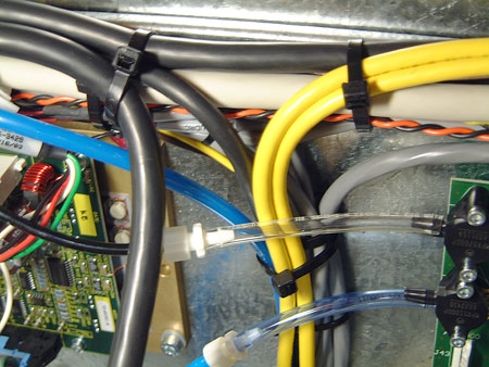 |
Order kit number 512-00066. Kit includes fitting and clear pneumatic tube. The fitting connects to the pressure side (top pipe) of the U74 sensor on the MCE board. | N/A | Next failure |
| CA00663 | May 2003 | Replacement carriage driver board for MCE devices. 503C01525B replaces 10-4935C | Order kit number 512-00041 to replace failed 10-4935C. Kit includes carriage driver board and cables. | 3(MCE) | Next failure |
| E897 | Oct 2002 | Plate sensors on load ramp, load table, and unload table lose connection due to fretting on the contacts between the cable and sensor. Replacement high flex cables have more reliable connectors. Sensors must be replaced in case of corrosion caused by previous connectors. | See Replacing Sensors and Cables - FCO E897
for procedures.
Base Trendsetter 400/800 - kit #512-00001 Trendsetter 3244(S/N S162 and lower) - kit #512-00002 |
19 (TS8)
31 (TS3) |
Next failure |
| E921 | Jul 2002 | Hose and cable length increased from 3m to 7.6m for UDRC so that unit can be moved farther away to reduce noise. Updated 4/8 Page,Debris Removal Kit,UDRC-B (02-4468A-C) | N/A | Next failure | |
| E445 | Jan 2002 | Improved debris nozzle(50-2117C) is less likely to clog the vacuum sensor port with ablative debris. Click on the photo below for old and new versions of nozzle.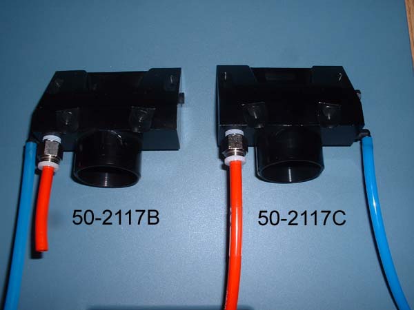 |
Order kit 05-0246 - includes nozzle, air jet plate, tube and fitting Install procedure |
N/A | Next failure |
| E492 | Mar 2002 | Current drawn by the carriage amp can insufficient to reliably maintain PS3 operation, resulting in a cyclic DC on/off condition. | Add newly created adapter cable 10-5067A in-line with the existing PS3/4-CA cable in the common power box to draw minimum current load from PS3. See FCO E492 procedure. | N/A | Next failure |
| E453 | Oct 2001 | Update to DHU installation kit.
Note: Replaces E246 |
See FCO E453 for kit number and installation procedure. No desiccant box. | N/A | Next failure |
| E405 | Oct 2001 | Replacement of Morgan cabinet with UDRC-B photo | See debris removal website for information on parts, maintenance, etc | 15(TS8) | Next failure |
| E010 | Jan 2001 | Revised mechanical design
of air jet plate to eliminate loctite.
See Air Jet Plate Assembly Drawing. |
See Trendsetter 800/400 Upgrade procedure, particulate ablative media. | 10(TS8) | Next failure or debris removal upgrade |
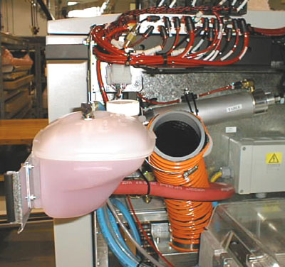
| D874 | Oct 2000 | If the old reservoir system springs a leak,
replace using kit
#05-0183
.
For machines with new reservoir system, add strainer basket (#57-8167).
Addition of strainer basket applies to all machines prior to TE0080 and
Px0030.
|
See
Water reservoir replacement procedure
. Check for strainer basket.
 |
N/A
|
Next failure
To add strainer basket, Next visit |
| D547 | Jun 2000 | Version C of TEE board, 10-3627, has new
pressure sensors. Service installations of version C board require
firmware version 2.40. Version B boards can be used until stock runs
out. Note: Replaces C039 |
Check board layout. See 10-3627C
assembly drawing.
See FCO D547 |
Next failure | |
| D587 | May 2000 | Low profile LEC (with lead-in chamfer) to
alleviate plate loading problems. Applies to SNs TE001 - TE035.
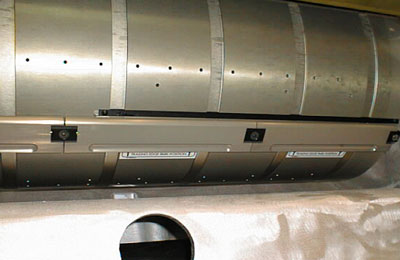 |
Replace LECs only if adjustment of LECs does not fix plate load failures. Replace all six with part number 50-2114A (clamp body with dowels). See Low Profile Clamps section in Speed Upgrade Procedure - TS8 devices. | 2 (TS8) | Next failure |
| C890 | Jun 1999 | New part number for servoamp: 15-3330A replaces 15-3114A. Identified with blue dot. | Replace only if a problem arises or you cannot
calibrate the servo amp using the "drum cal" command.
Note: Firmware that supports "drum cal" (drum module 1.11 or higher) is a pre-requisite for implementing this FCO. |
Next failure | |
| C674 | New drum roller (57-2209D) with a smaller diameter on the ends. | Replace drum roller. | 17(TS3) | Next failure | |
| C144 | Feb 1998 | The thermal DPE board and the PHI board are being replaced by the new FDPE (Fast Data Path Electronics) board. | To replace the DPE board:
|
Next failure |
| FCO | Date Posted | Description | Service Actions | 100 Label # | Priority |
|---|---|---|---|---|---|
| CA03738 - MCE | Mar 2004 | Change TEC micro-switches to optical sensors on MCE devices to improve reliability. Applies to TM327 and lower. | Order kit number 512-00112A.
TEC Optical Sensor Upgrade Procedure (TSM) |
11 (MCE) | Next PM |
| CA01804 | Sep 2003 | Remove MOVs and spark gaps between line and
ground.
Note: Replaces B931 |
Creo MPE devices are no longer being shipped with metal oxide varistors (MOVs) and spark gaps between line and ground. The MOV assembly should be removed from units in the field (serial numbers TE 799 and earlier) at the next PM visit. Remove the screws and slide out the power entry box (11-0589B). Remove the three MOV assemblies (10-4018A) by loosening the screws on the terminal block. Fasten the power entry box back in place. Mark the 100 label. | N/A | Next PM |
| C716 | Feb 1999 | Wave washer between the TEC cylinder and slider bracket may break. Solution: remove wave washer. | Field upgrade. See procedure in C716 | N/A | Next PM |
| FCO | Date Posted | Description | Service Actions | 100 Label # | Priority |
|---|---|---|---|---|---|
| CA12621 | Nov 2007 | New yellow Propylene Glycol coolant(090-00326A) replaces pink Ethylene Glycol coolant(82-1032A) Applies to serial numbers TG0365 and lower, and NG0262 and lower. |
Some regions or customers may have HSE regulations that restrict the use of ethylene glycol. Any Trendsetter or Trendsetter NEWS customer that requests HSE-friendly propylene glycol should be upgraded. GMCE devices marked with 100 label #2 have hoses with Viton seals (50-1925E and 50-2450B) installed and are ready to use the new coolant. For other devices, order one of the following upgrade kits: 512-00451A for single head devices Procedure 512-00452A for dual-head devices Procedure |
4 (GMCE) | FYI |
| CA00063 | Oct 2002 | TEE Board replacement kit includes TEE board plus necessary LUER fittings. | Order kit number 518-00003 when you have to replace a TEE board. | N/A | FYI |
| E740 | Aug 2002 | Processless Debris Removal Upgrade, TS4/8 Page,
UDRC-LC
Note: name changed from Processless to Chemistry-Free (Sep 2002) |
Kit number 02-4497A-A. See Trendsetter 400/800 Processless Plate Imaging System, UDRC-LC Installation/Upgrade Procedure for information on kit ordering, firmware requirements, and site requirements for UDRC-LC. | N/A | FYI |
| E833 | Jul 2002 | Updated 4/8 Page,Debris Removal Kit,UDRC-B | Kit number 02-4468A-B. See Trendsetter 800/400 Upgrade procedure, particulate ablative media for information on ordering UDRC-B. | N/A | FYI |
| E404 | Jul 2002 | Common drum (50-2111) used for TS8 and NEWS
Assembly Drawing. |
Registration pins for old drums (50-1854) are obsolete. New drums can be identified by crescent-shaped brass counterweight mounted on endbell. Drum requires belt tension of 70Hz. For parts information, see Engine. | 17(TS8) | FYI |
| E243 | Jan 2002 | Fanbox changes - see photos in FCO E243. | To see how the latest version of the fanbox affects service, see FCO E243. | 16(TS8) | FYI |
| E041 | Oct 2001 | Redesign of the top panel to accommodate a new Southco latching mechanism. See page 2 of top panel assembly Drawing. | Service needs to order the new hinge when replacing the top panel. For parts information, see Top Panel Kit. | N/A | FYI |
| E114 | May 2001 | New SCSI cable. Upgrade kit 05-0219
Implemented on TE242, PX072 and above and all TN. |
Replace SCSI cable. For details, see FCO_E114. | 12(TS8) | FYI |
| E115 | Apr 2001 | Introduction of Universal Power Cord
See 16-4451 assembly drawing. |
For new installs only. See FCO E115. | 11(TS8) | FYI |
| D845 | Nov 2000 | Debris removal for Trendsetter 3244+V to
provide 1.3 min imaging time. Provides improved drum brake system.
Spectrum requires a new rotary joint. |
See
Trendsetter 800/400 Upgrade procedure, particulate ablative media.
Also see the following BOMs: Debris removal hooks kit Debris removal kit Drum motor brake kit |
6 (TS8) | FYI
As needed |
| D210 | Oct 1999 | EMI filter relocation. Applies to Spectrum only built in Kiel | See instructions in FCO D210. | 26 | FYI |
| C942 | Jun 1999 | Release of Encoder Cleaning
Kits:
• Encoder/lens cleaning kit (04-0012B) • Encoder cleaning kit (04-0014A) (includes 04-0012B) |
See Optical encoder cleaning procedure | FYI | |
| C371 | Jul 1998 | The current hotlink cable (16-3532) is replaced with a stranded core coax cable (16-3532A-A) to improve reliability. | Replace as required on S207 and lower | 10(TS3) | FYI |
| C341 | Jun 1998 | In order to support the higher drum speeds required by the 3.0 minute thermal head, early Trendsetters must be retrofitted with stiffer engine mounts. | Implemented on SP1 and S150. | FYI | |
| C191 | Mar 1998 | Optional external alarm kit | FYI | ||
| C051 | Jan 1998 | New pushbutton on the Trendsetter 3244
OIF board(10-1420B) and cable(10-3187) |
Brown wire connects to button LED pin X1
Red wire connects to button LED pin X2 Black wire connects to contact pin 13 White wire connects to contact pin 14 | 3(TS3) | FYI |
| B812 | Jul 1997 | Major changes to the power box and mainframe so that the base Trendsetter 3244 can be upgraded with the Proofer or Autoloader option. | Instructions to upgrade fan cooling system in the field Field upgrades required for the following 6 units even if they are not to be converted to Trendsetter Spectrum: S67, S68, S69, S70, S72, S73 | FYI | |
| B713 | Jul 1997 | New version of reed switch tester (10-3622B). New tester has a longer cable and includes a hall effect tester. | FYI | ||
| B624 | Nov 1996 | Removal of the thermal blower mesh to prevent
restricted airflow through head.
Applies to Trendsetter 3244 serial numbers S1 to S65. |
Trendsetter 3244 fanbox upgrade | FYI | |
| B104 | Nov 1996 | Latch upgrade | FYI |