Home | Contact Us | Submit Troubleshooting Info | Search | Help
Output | Software Solutions | Proofing | Color, Screening and Calibration | Scanning | Digital Photography | Consumables | POS
Home | Contact Us | Submit Troubleshooting Info | Search | Help
Output | Software Solutions | Proofing | Color, Screening and Calibration | Scanning | Digital Photography | Consumables | POS
Board | Cables | CR Installer | Compatibility | Connectivity | DCAPI | Diagrams | Firmware | NVS Parameters | Parts | Procedures | PSRM | Test Plot | Training | Troubleshooting | FAQs | Workstation
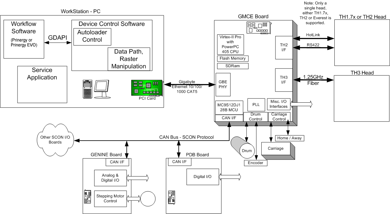
The Gibabit Master Control Electronics (GMCE) board is a systems control board that evolved from the Turbo Master Control Electronics (TMCE) board. Because the GMCE board communicates with the device workstation via a single ethernet cable, the SCSI cable and the two serial cables are not needed.
Advantages of the GMCE board include:
There are some minor cable changes (length only) between TMCE and GMCE. Major changes include:
The GMCE board (503-08443F) looks similar to a TMCE board but there are some significant internal differences that you must be aware of:
 |
J1: TH2 hotlink
J2: TH2 RS-422 control J4: J5: J6: J14: J17: J18: J38: UDRC |
J39:
J40: J42: WS_COMM gigabit ethernet J47: J53: J56: J69: USB backup U126: TH3 fibre optic |
For details on the LED status, see GMCE Firmware and LED Reference.
The GMCE does not have battery-backed RAM like the TMCE—the NVS parameters are downloaded to the GMCE when it is reset.
The parameters are stored on the workstation in the C:\Creo\Firmware\GMCENVS00.bin file. This file name is in the
CreoBootp.ini file. For dual-head systems there is another NVS file called GMCENVS01.bin for the slave GMCE board.
Whenever a parameter is changed by the product firmware or by a diagnostic command such as >>set media 1 name…, the
entire NVS parameter set is uploaded to the workstation and replaces the contents of the GMCENVS00.bin file.
Some resulting actions of this architectural change include:
There are two main firmware components that run on the GMCE board:
Some resulting actions of this architectural change include:
To search for GMCE commands, parameters, and errors, use the MCE/GMCE search page.
To download and install firmware simulators, see the Control/settings page.
This configuration file defines the connection between the GMCE board and the workstation, and what firmware and NVS files to use.
This file also contains the IP address of the GMCE board(s). Service Shell’s Host Configuration Wizard parses the CreoBootp.ini file to get
this information to make setting up Service Shell easier. A software component called the Creo Bootp Server runs on the workstation.
It reads this configuration file and coordinates the downloading of the NVS data and firmware binary.
This is a sensitive file and should not be edited directly. It is written by the GMCE Core Firmware Installer and the Product
Firmware Installer.
On the TMCE, you use the plot command to image test plots, including GC plots. On the GMCE, you must use the Test Plot Applet (TPA) in
Service Shell to accomplish this. This is because all raster manipulation is performed on the workstation, in a software component called Post Screening Raster Manipulation (PSRM). The PSRM component performs orthogonal and geometric correction on the data before it
passes it to the GMCE board.
The plot command is still available, but only supports a small subset of plots available in TPA and provides no orthogonal and
geometric correction. As a result, the series plot script in Service Shell cannot be used. TPA must be used for all series plots.
The purpose of PSRM is to:
The SRD is in GDAPI data format and is generated by a raster source such as workflow software (Prinergy or Prinergy Evo). The control
software (DCAPI, Magnus800 Controller) provides PSRM all the necessary parameters on how the screened raster data is to be manipulated,
as well as the starting and ending of jobs.
THRD is to be sent to a raster sink via high-speed interfaces. The raster sink can be GMCE, TMCE, IHIF(TBD), or a disk file.
PSRM effectively provides a common datapath for GMCE and TMCE systems. As a result, the difference between GMCE and TMCE systems is
transparent to the output device operator.
The Device Control Application Programming Interface (DCAPI) provides a common interface to the output device for Print Console and
Service Tools. The DCAPI is a means of encapsulating common high level commands used to control output devices. This programming interface
can be used by workstation applications to control the behavior of the device by sending commands like 'get the drum speed', or 'load this plate', or 'image this test plot'.
Why do we need it? We were starting to have numerous applications such as device controllers and service tools that needed to control
the device, however each device required different commands and protocols to control it, and in many cases these were not well defined.
Having one clean, dedicated interface that a programmer of these applications can use to communicate with any device – MCE, MPE, CIL based
- goes a long way towards reducing code duplication, lower maintenance and quicker development cycles.
So for example, a service tool that needs to load a plate only has to call a single command, while DCAPI does all the internal work of
what parameters are relevant, how to structure them, and whether to send them to the device using Rcon, WSRIF or CIL protocol.
Each controlled release for GMCE-based products has a Controlled Release (CR) Installer. This installs all the software and firmware
components in that controlled release by invoking installers for each individual component, including the Creo Bootp Server,
GMCE Core Firmware, product firmware, and satellite firmware.
The CR installer must always be used to install the software and firmware components on GMCE devices.
For Thermal Head firmware, the CR Installer invokes the Service Shell upgrade script.
There are several key changes to the device workstation that include:
The device workstation requires an Intel Pro 1000MT, 1GB network card to communicate with the GMCE board via the ethernet cable (CAT 5E or CAT 6) that supports Jumbo Frame settings. Only the Intel Pro board is supported. To configure the Intel Pro 1000MT ethernet card on a workstation, see the GMCE Intel Pro/1000 MT Server Adapter Installation, Configuration, and Testing document.
For Magnus VLF, see also GMCE IP Addressing Scheme for Magnus VLF GMCE Devices and Workstations
The GMCE board is installed on all Series II Magnus VLF devices. For more information on Series II devices, see the Overview page. For Series II specific device upgrades, see the Procedures page.
The GMCE board is installed on all Trendsetter 400/800 III devices (serial numbers TGxxxx) and Trendsetter NEWS with serial numbers NGxxxx.
For training on the GMCE and supporting hardware and software, see the Trendsetter or Magnus VLF Reference page.
Contacts | DCAPI | GMCE | PSRM | Workstation
E-mail the GMCE Experts with your questions or problems relating to GMCE. Your e-mail will be directed to:
Also, submit any troubleshooting cases that you would like to share with other CSEs stating the problems and solutions.
door unlock command is issued. See CR4.01 patch 5.For PSRM troubleshooting errors, see the PSRM Errors document (719-00648A).
 When the communications layer (DCAPI) is shutting down, Print Console sometimes crashes.
Workaround: Click OK in the Print Console “crash” dialog when the DCAPI server is shutting down. Print Console will then shut down.
When DCAPI shuts down and Print Console handles the shutdown correctly, jobs will be cancelled because communication with the output
device is lost.
If the network connection between the device and the workstation workstation is lost after an idle period, like overnight or other quiet
period, then it could be that the network card is configured to save power by shutting down.
Solution: Go to Network Places for each network card and select Properties/Configure/Power Management.
Uncheck the 'Allow the computer to turn off this device to save power option'.